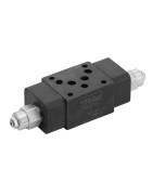
Zawory hamujące-przeciążeniowe (counterbalance)
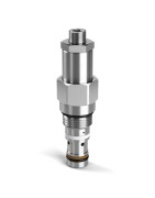
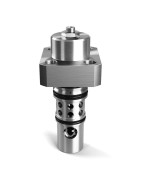
Parker counterbalance valves are screw-in type cartridge valves that control the pressure at an actuator controlling its motion. Uses include controlling over-running loads in cylinders and motors.
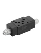
-
Motor Control Valves
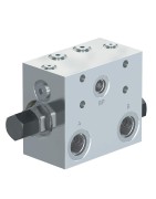
Load Holding, Hose Break and Overrunning Load Protection can be easily achieved with Parkers Low-Speed-High-Torque motors with the use of direct flange mounted MMB counterbalance packages. Space saving and plumbing reduction can be achieved when used with Parker TB, TE, TF, and TG motors. Both motor control packages are available with two pilot ratio options, and can be supplied vented, non-vented and with or without a motor brake release port. Superior counterbalance functionality is accomplished with the use of single or double MHC series load and motor control valves.
Parker’s offering of motor mounted counterbalance control valves allow design flexibility in the most demanding applications and markets including and not limited to: Refuse, Oil and Gas, Material Handling, Construction, Drills, Presses, Mixers, Agriculture, Balers, Combines, Load Holding, Hose Break Protection, Overrunning Load Control, Hydrostatic Drives, etc. -
Standard Pilot Vented Load Control Valves
Parker’s counterbalance, or load control, valves are available either vented, or non-vented style. The vented valves are available in flow ranges from 5 gallons per minute up to 48 gallons per minute, and pressures up to 5000 psi.
Typical uses of these valves are in applications where:
• Loads are lowered and a smooth operation is required to prevent a runaway condition
• Loads are handled using a cylinder operating in an over center condition
• Load drift needs to be eliminated due to control valve spool leakage
Sizing a counterbalance valve needs care in that the flow required is usually higher than system pump flow, as in the case with a cylinder application (retract flow could be twice the system flow). Oversizing the valve could cause instability. When the pressure setting is critical, a vented load control is preferred. Pressure in the spring chamber of the valve is vented to atmosphere and therefore independent of any back pressure from the tank line.
The pilot ratio is the ratio of the pilot area versus the differential area poppet. Thus, the higher the pilot ratio, the less pressure that is needed to assist the load pressure in unseating the poppet. This means there is less restriction to the overrunning load, resulting in less horsepower required and more control of the load. So higher pilot ratio equates to less restriction to the overrunning load, less control and less horsepower required. Lower ratio equates to more restriction to the overrunning load, more control and more horsepower required. The pilot ratio decision is one of Horsepower versus Control. For reference the most popular ratio is 6:1.
Parker offers counterbalance valves with adjustable and non-adjustable pressure settings. Non-adjustable, or shimmed version, is recommended for most applications as it prevents tampering or improper adjustment by uneducated users. -
Standard Pilot Assisted Load Control Valves
Counterbalance valves are devices used to control cylinder and motor loads helping to restrict overrunning loads, assist with controlling speed and position for varying loads, and they are also used as load holding devices with built in thermal relieving functionality. Standard counterbalance valves are pilot operated devices that allow free flow in one direction and restricted flow in the opposite direction. The load is held in place until the counterbalance setting is overcome by sufficient pressure generated by the pump, thermal expansion, or from external forces acting on the actuator. Once the pressure falls below the required setting, the valve closes and holds the load in place. In order to save horsepower, pilot pressure assists in the opening of the valve allowing the load to be controlled with a lower than load induced pressure as long as the available pilot pressure is greater than the ratio between the valve setting and the selectable pilot ratio. Standard counterbalance valves are non-vented meaning the control spring chamber is connected to the valve outlet which will cause any downstream pressure to be additive the valves pressure setting. If excessive downstream pressure may be present or if the counterbalance pressure setting is critical, Parker also offers several series of externally vented counterbalance valves.
Parker’s CB101, MHC-010-S, MHC-022-S, and E2 series of counterbalance valves are all standard non-vented load and motor control valves. Each series has multiple pilot ratio options, adjustment styles, and available pressure ranges. They can also be supplied with fixed factory settings, or with tamper proof caps. Typically higher pilot ratios are used for simple load holding applications where the moving load is controlled by external means and the main purpose of the counterbalance is to hold the load in position when not being operated, and to provide thermal and hose-break protection. Lower pilot ratios are typically used to assist in applications where cylinder or motor speed and positioning needs to be controlled with varying loads.
MHB-015-L and MHB-030-L are counterbalance valve assemblies consisting of an in-line or gasket mounted body and one or two counterbalance valves. In-line mounted bodies can allow the counterbalances to be placed remotely on the machine and plumbed from a distance or directly to an actuator using hose, pipe, or tubing. Gasket mounted version reduce required plumbing and also leak points by allowing the counterbalances to be mounted directly on the motor, cylinder, or rotary actuator.
Parker’s extensive line of counterbalance load and motor control valves allow design flexibility in the most demanding applications and markets including and not limited to: Power Units, Refuse, Oil and Gas, Material Handling, Construction, Drills, Presses, Mixers, Agriculture, Balers, Combines, Load Holding, Hose Break Protection, Overrunning load control, etc. -
Counterbalance Valve Series ZNS
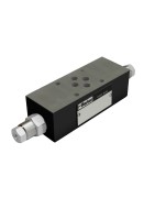
Parker counterbalance valves series ZNS in sandwich design control the actuator movement at overrunning loads via a leak-free poppet valve. Thereby they enable a reliable operation and a linear lowering speed of the cylinder.
The return flow from the actuator is piloted and controlled by the inlet flow to the actuator, ensuring a cavitation-free lowering of the load. The counter balance valve operates as a pressure relief valve. The setting pressure is lowered by the pressure in the inlet line.
Please note:
To ensure safe load holding the setting pressure should be approximately 30 % higher than the max. load pressure.
Markets:
• Industrial
Features/Benefits:
• Available in two sizes:
ZNS*01 – NG06 (CETOP 03)
ZNS*02 – NG10 (CETOP 05)
• Controlled movement loads
• Load holding via leak-free poppet valve
• Secondary relief protection for the actuator
• Short delivery time -
COUNTERBALANCE SANDWICH VALVE Series CB
Series CB Counterbalance valve controls the actuator movement with overrunning loads.
The return flow from the actuator is piloted and controlled by the inlet flow to the actuator, ensuring a cavitation-free lowering load.
The counterbalance valve operates as a pressure relief valve. The setting pressure is lowered by the pressure in the inlet line. To ensure safe load holding the setting pressure should be approximately 30% higher than the maximum load pressure.

