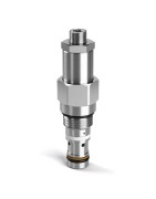
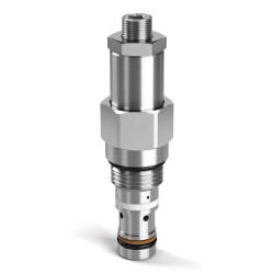
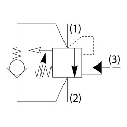
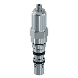
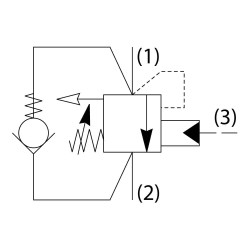
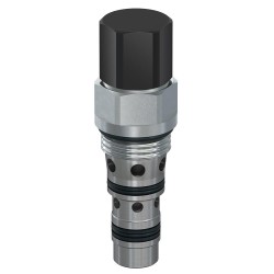
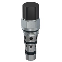
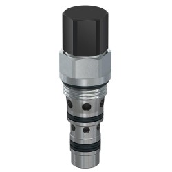
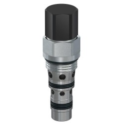
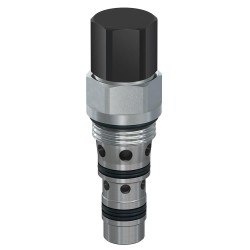
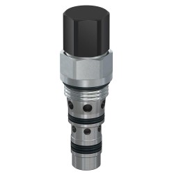
Standard Pilot Vented Load Control Valves
Parker’s counterbalance, or load control, valves are available either vented, or non-vented style. The vented valves are available in flow ranges from 5 gallons per minute up to 48 gallons per minute, and pressures up to 5000 psi.
Typical uses of these valves are in applications where:
• Loads are lowered and a smooth operation is required to prevent a runaway condition
• Loads are handled using a cylinder operating in an over center condition
• Load drift needs to be eliminated due to control valve spool leakage
Sizing a counterbalance valve needs care in that the flow required is usually higher than system pump flow, as in the case with a cylinder application (retract flow could be twice the system flow). Oversizing the valve could cause instability. When the pressure setting is critical, a vented load control is preferred. Pressure in the spring chamber of the valve is vented to atmosphere and therefore independent of any back pressure from the tank line.
The pilot ratio is the ratio of the pilot area versus the differential area poppet. Thus, the higher the pilot ratio, the less pressure that is needed to assist the load pressure in unseating the poppet. This means there is less restriction to the overrunning load, resulting in less horsepower required and more control of the load. So higher pilot ratio equates to less restriction to the overrunning load, less control and less horsepower required. Lower ratio equates to more restriction to the overrunning load, more control and more horsepower required. The pilot ratio decision is one of Horsepower versus Control. For reference the most popular ratio is 6:1.
Parker offers counterbalance valves with adjustable and non-adjustable pressure settings. Non-adjustable, or shimmed version, is recommended for most applications as it prevents tampering or improper adjustment by uneducated users.
