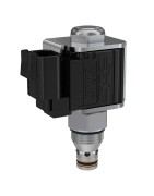
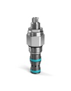
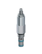
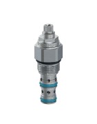
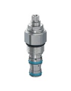
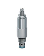
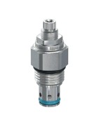
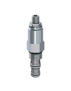
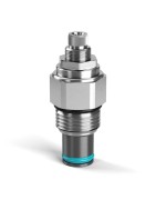
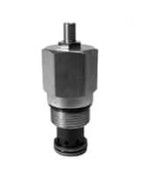
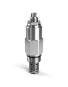
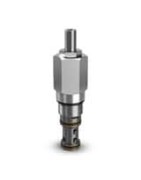
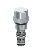
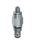
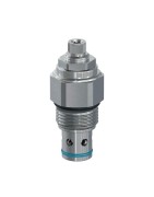
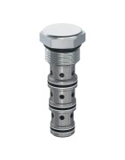
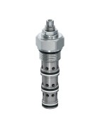
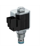
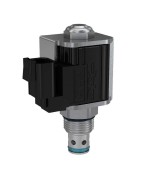
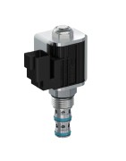
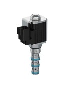
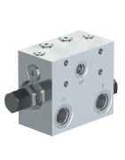
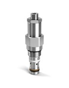
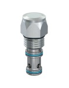
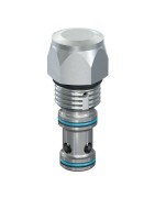
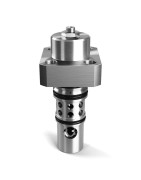
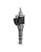
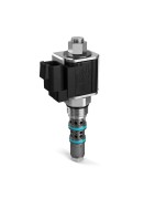
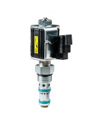
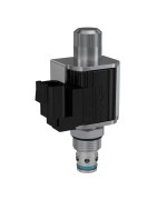
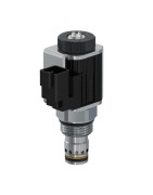
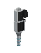
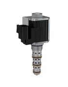
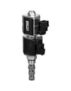
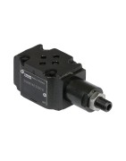
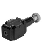
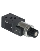
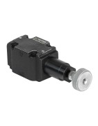
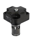
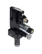
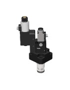
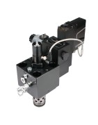
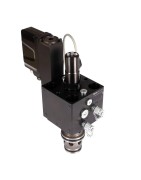
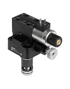
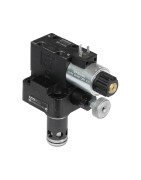
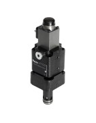
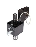
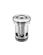
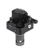
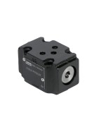
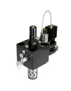
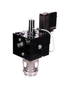
Zawory nabojowe
Parker's manifold cartridge valves are an innovative, yet simplified alternative to solenoid operators and stud mount valves. Our cartridge valves offer numerous features and benefits including a space-saving approach, less manifold machini
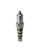
-
2-drogowy, dwukierunkowy zawór elektromagnetyczny typu...
2-drogowe, dwukierunkowe, grzybkowe zawory elektromagnetyczne firmy Parker mają sprawdzoną konstrukcję, która zapewnia bardzo niski poziom wycieków, gdy przepływ jest blokowany w dwóch kierunkach oraz zminimalizowany spadek ciśnienia w pozycji przepływu swobodnego. Zawory mogą pracować w układach hydraulicznych o natężeniu przepływu do 285 l/min i ciśnieniu do 350 barów w konfiguracjach normalnie otwartych lub normalnie zamkniętych. Niektóre 2-drogowe, dwukierunkowe, grzybkowe zawory elektromagnetyczne firmy Parker mają wbudowane odciążenia termiczne ustawione na 36 barów, ale wszystkie idealnie nadają się do zastosowań związanych z odciążaniem lub utrzymywaniem obciążenia, które wymagają niskiego poziomu wycieków zapewnianego przez rozwiązania typu grzybkowego przeznaczone na rynki urządzeń mobilnych, przemysłowych lub produkcyjnych.
Rynki:
• Przemysł
• Produkcja
• Urządzenia mobilne
Cechy/zalety:
• Krótki czas reakcji
• Jednoczęściowa obudowa kartridżu.
• Dostępne wbudowane odciążenie termiczne.
• Wszystkie części zewnętrzne ocynkowane.
Zastosowania:
• Zastosowania z blokowaniem w dwóch kierunkach
• Obwody odciążające
• Utrzymywanie obciążenia
• Układy podnoszenia
Dodatkowe informacje techniczne:
2-drogowe zawory grzybkowe firmy Parker to zawory elektromagnetyczne sterowane pośrednio o niskim poziomie wycieków. Podobnie jak zawory zwrotne, zawory te blokują przepływ w jednym kierunku przy bardzo małych przeciekach (5 kropli na minutę lub mniej). Po aktywacji zawory te umożliwiają przepływ. Zawory te są zazwyczaj wybierane ze względu na ich niski stopień przecieków oraz możliwość stosowania do wyższych przepływów. Zawory grzybkowe są często stosowane razem z siłownikami jednostronnego działania lub w funkcji odciążania. Są one dostępne w wersjach normalnie zamkniętej i normalnie otwartej oraz w wersjach o krótkim czasie reakcji.
Dwudrogowe, dwupołożeniowe zawory grzybkowe firmy Parker składają się z grzybka głównego, grzybka pilotującego, sprężyny i cewki elektromagnesu.
Wersja normalnie zamknięta tych zaworów grzybkowych działa jako zawór zwrotny, gdy elektromagnes nie jest zasilany. Blokuje przepływ w jednym kierunku, umożliwiając przepływ w kierunku przeciwnym Po włączeniu zasilania cewki grzybek jest sterowany do pozycji otwartej (podnosi się) i umożliwia swobodny przepływ w uprzednio zablokowanym kierunku, zwykle w kierunku od strony bocznej zaworu do jego końcówki.
W przypadku wersji normalnie otwartej tych zaworów grzybkowych, po wyłączeniu zasilania cewki możliwy jest swobodny przepływ z bocznego przyłącza zaworu (przyłącze 2) do końcówki zaworu (przyłącze 1). Włączenie zasilania cewki powoduje przesunięcie grzybka i zablokowanie przepływu w kierunku 2 do 1.
Zasada działania: normalnie zamknięty zawór grzybkowy utrzymywany jest w gnieździe przez sprężynę, blokując przepływ pilotowy. Dzięki temu ciśnienie na przyłączu wlotowym (przyłącze 2) może utrzymać grzybek w gnieździe, uniemożliwiając przepływ przez zawór (od przyłącza 2 do przyłącza 1).
Jeśli ciśnienie na końcówce kartridżu (przyłącze 1) jest wystarczające, aby pokonać siłę sprężyny i wypchnąć grzybek z gniazda, możliwy będzie przepływ przez przyłącze 1 do przyłącza 2. Po włączeniu zasilania cewki grzybek sterujący jest podnoszony z gniazda, uwalniając ciśnienie wewnątrz grzybka do przyłącza 1. Powoduje to nierównowagę ciśnienia na grzybku głównym, a w konsekwencji jego podniesienie i umożliwienie przepływu z boku na końcówkę (z 2 do 1). Ponieważ zawory te są sterowane pośrednio, konieczna jest minimalna różnica ciśnień (25–50 psi) oraz przepływ między przyłączami 2 i 1, aby pokonać siłę sprężyny i podnieść grzybek.
Pilot zaworu normalnie otwartego jest utrzymywany poza gniazdem przez siłę sprężyny. Pilot jest drenowany do przyłącza 1, powodując niezrównoważenie ciśnienia, które sprawia, że grzybek główny się porusza. Ta różnica powoduje podniesienie grzybka, umożliwiając przepływ z boku zaworu na jego końcówkę (z 2 do 1). Zawory grzybkowe są sterowane pośrednio, więc minimalna różnica ciśnienia (25–50 psi) między przyłączami 2 powoduje pokonanie siły sprężyny i przemieszczenie pilota zaworu i grzybka głównego do ich gniazd, blokując w ten sposób przepływ z przyłącza 2 do 1. Jeśli występuje ciśnienie na końcówce kartridżu (przyłącze 1), pokonuje ono siłę sprężyny i siłę elektromagnesu, wypychając grzybek z gniazda i umożliwiając ograniczony przepływ przez nabój (z 1 do 2). -
Pilot Operated Pressure Reducing Valves
Pilot operated pressure reducing valves are designed for continuous duty applications. Due to their stability and low pressure rise, the pilot operated pressure reducing valves are the best option for setting the pressure of a hydraulic system sub-circuit.
• Spool design provides low hysteresis
• Low parasitic loss
• High pressure capable
• Multiple pressure ranges available for more accurate pressure control
• Adjustable and tamperproof versions available
• All external parts zinc plated
• Hardened, precision ground parts for durability
• “D”-Ring seal standard on Winner's Circle
• Low profile adapter for minimal space requirements
Common circuit applications include: brake release, dual pressure circuits, pilot pressure control and downstream pressure control. -
Direct Acting Pressure Reducing Relieving Valves
Direct Acting Reducing/Relieving valves are applied in a circuit in order to reduce system pressure to the setting of valve to limit the pressure available to a specific branch of a hydraulic circuit. The direct acting function of the normally open valve allows the spool to operate directly against a control spring that is set using the valves internal adjustment setting. As hydraulic pressure is applied to the valve inlet, the spool will shift closed against the spring to limit the pressure that is available to the regulated port to the control setting. The valve will also function as a relief valve to the regulated port in the event of a rise in downstream pressure, protecting the regulated branch of the circuit from pressure spikes. Direct acting reducing/relieving valves are intended or intermittent duty applications with lower duty cycles that will not stress the mechanical operation of the valve. For best performance in the direct acting reducing/relieving valve, the inlet pressure setting should not exceed 1000 PSI (69 Bar) above the reducing valve setting, as high pressure differential could result in instability in the direct acting product. For continuous duty applications or applications where a high differential is required, the pilot operated version of this product should be considered as an alternative solution.
Typical applications are in mobile & industrial equipment, where a branch of the system is intended to operate at a lower setting than high system pressure. Hydraulic functions such as brake circuits, clamping or clutch circuits, suspension systems, street sweepers, or seeding and planting rows in agricultural equipment are common applications for these products.
• Hardened, precision ground parts for durability
• All External parts zinc plated
• Adjustable and tamperproof versions available
• Multiple pressure ranges available for more accurate pressure control -
Zawory redukcyjne i odciążające sterowane pośrednio
Rodzina sterowanych pośrednio zaworów redukcyjnych i odciążających firmy Parker zapewnia doskonałą regulację ciśnienia w zastosowaniach, w których potrzebne jest konkretne ciśnienie regulowane lub otwarcia w celu zapewnienia precyzyjnego działania funkcji wymagających regulowanego ciśnienia do 380 barów (5500 psi) i natężenia przepływu do 150 l/min (40 gal/min). Sterowane pośrednio zawory redukcyjno-odciążające firmy Parker zaprojektowano do kilku zakresów ciśnień, aby zapewnić wyższy stopień kontroli dzięki różnym dostępnym sposobom regulacji. Dodatkowa stabilność uzyskana dzięki sterowaniu pośredniemu sprawia, że zawory te doskonale się nadają do obsługi wrażliwych funkcji, takich jak podnoszenie lub docisk, zaciskanie lub hamowanie w różnych typach maszyn na rynkach mobilnym i przemysłowym.
Rynki:
• Rolnictwo
• Sprzęt budowlany
• Przemysł
• Produkcja
• Urządzenia mobilne
Cechy/zalety:
• Dostępność wielu zakresów ciśnień pozwala na dokładniejszą regulację ciśnienia.
• Kompaktowe rozmiary ograniczają wymagania przestrzenne
• Dostępne wersje regulowane i odporne na ingerencję.
• Możliwość pracy pod wysokim ciśnieniem.
• Wszystkie części zewnętrzne ocynkowane.
Zastosowania:
• Hamulce
• Opaski zaciskowe
• Układy zawieszenia
• Układy podnoszenia/docisku
Dodatkowe informacje techniczne:
Typowe zastosowania to urządzenia mobilne i przemysłowe, w których gałąź układu ma działać przy ustawieniu niższym niż wysokie ciśnienie układu. Funkcje hydrauliczne, takie jak obwody hamulcowe, obwody zaciskowe lub sprzęgła, układy zawieszenia, zamiatarki uliczne, lub rzędy siewu i sadzenia w sprzęcie rolniczym są typowymi zastosowaniami tych produktów. -
Pilot Operated Ventable Relief Valves
Ventable relief valves are pilot operated, spool type pressure controls. Like other pilot operated relief valves, the ventable relief has a main pilot spring chamber, and a bias spring chamber separated by a pilot orifice. The internal adjustment controls the main pilot spring setting. When pressure in the system builds above the setting of the main pilot setting, the pilot seat will lift allowing the spool to travel to the open position passing flow. What makes ventable relief valves unique is the valve offers an isolated vent chamber that is connected to the bias spring chamber. This allows for the valve to open at a lower pressure than the setting of the main spring.
The circuit designer has the ability to apply an external control valve or valves to set the operating pressure of the bias spring that must be overcome to allow the valve to open. This is an ideal solution in applications that may require variable pressure settings in normal operation.
One must consider the leakage component when applying any pilot operated spool type relief valve, as by design, the spool will pass a small leakage flow.
Typical applications are in mobile & industrial equipment, where multiple pressure settings may be required. Applications such as press or lift circuits where multiple pressure settings may be required.
• High flow capacity
• Full tank line back pressure capability
• Excellent flow pressure characteristics for consistent pressure setting
• Ideal for pump relief and remote control or unloading via vent (port 3)
• Integral 250 micron pilot flow filter
• Hardened working parts for maximum durability
• Adjustable and tamperproof versions available
• All external parts zinc plated
• Low override curve
• Ball-type pilot for added stability
• High accuracy - pilot operated design
• Hardened, precision ground parts for durability
• Compact size for reduced space requirements
• All external parts have yellow zinc dichromate. This coating is ideal for salt spray applications. -
Direct Acting Differential Area Relief Valves
Parker Hannifin's RD and RDH line of differential area relief valves provide excellent pressure control in applications where a fast acting, low leakage relief valve is necessary. Parker's family of differential relief valves are available in three sizes (size -08, -10, and -16) with flow capability of up to 40 gpm. The size -16 family is limited to 3500 psi while the rest of the family is capable of 5500 psi. Unlike the direct acting family of relief valves, Parker's differential area relief valves are designed to have the pressure controlled at port 2 of the cavity. This ensures low leakage across the valve, essential in some holding applications. Designed using industry common cavities, the RD and RDH line of reliefs can easily be used in various system applications with ease.
Industries where commonly found:
• Turf
• Agriculture
• Aerial
• Construction
• Mining
• Industrial
• Truck -
Zawory nadmiarowe sterowane pośrednio
Zawory nadmiarowe sterowane pośrednio firmy Parker cechują się stabilną konstrukcją o małym spadku ciśnienia. Przeznaczone są do zastosowań ciągłych przy pracy o niższym poziomie hałasu hydraulicznego. Zawory mają niezawodną i kompaktową konstrukcję i mogą pracować przy ciśnieniu do 420 barów (6000 psi) i natężeniu przepływu do 400 l/min (106 gal/min). Zawory nadmiarowe sterowane pośrednio firmy Parker idealnie nadają się do ograniczania ciśnienia w układzie lub w standardowych zastosowaniach zaworów nadmiarowych w urządzeniach mobilnych i przemysłowych, takich jak urządzenia rolnicze, lotnicze, do przetwarzania odpadów, przemysłowe systemy bloków energetycznych, urządzenia górnicze i inne obwody regulacji ciśnienia płynów przeznaczone do pracy ciężkiej.
Rynki:
• Przemysł
• Produkcja
• Urządzenia mobilne
Cechy/zalety:
• Wysokie ciśnienie i natężenie przepływu.
• Konstrukcje kulowe i grzybkowe o niskim wycieku.
• Kompaktowa konstrukcja.
• Wewnętrzne filtry.
• Hartowane, precyzyjnie szlifowane części zapewnia trwałość
• Wszystkie części zewnętrzne ocynkowane.
Zastosowania:
• Ogranicznik ciśnienia w układzie
• Przyłącze/upust między przyłączami
• Wychylany upust
• Hamowanie silnikiem
Dodatkowe informacje techniczne:
Ta rodzina zaworów najlepiej nadaje się do układów o pracy ciągłej, w których wymagana jest praca zaworu poza okresami użytkowania przerywanego. Mogą być używane do utrzymywania ciśnienia w układzie przez długi czas. Dodatkowo w systemach, w których mogą występować duże szybkości zmian przepływu, zawory sterowane pośrednio mogą dostosować się do tych zmian bez nadmiernego wzrostu ciśnienia. Ze względu na obszary otwarcia przepływu przez zawór zawory suwakowe będą działać ciszej niż konwencjonalne zawory bezpośredniego działania. Należy również wziąć pod uwagę poziom wycieków, ponieważ suwak ze względu na swoją konstrukcję przepuszcza niewielki wyciek, natomiast zawór bezpośredniego działania nie przepuszcza znaczącego przepływu do momentu osiągnięcia ciśnienia otwarcia. Suwakowych zaworów nadmiarowych nie należy używać do utrzymywania obciążenia. -
Unloading Relief Valves
Parker’s RU101 and M04A4J offer design flexibility by allowing the use of hydraulic components to automatically control pump flow to one or more accumulators. These are low flow pilot valves that can be used to control higher pump flows in fixed displacement or load sense systems.
The RU101 is externally piloted and rated for flows up to 1 GPM and pressures up to 3000 psi. It is typically used with fixed displacement pumps and can directly unload flows up to 1 GPM or be used to pilot a logic element to unload higher pump flows. Once the accumulators are charged to the adjustable or factory preset maximum pressure, the pump will automatically unload back to tank. Due to the differential area design, when the pressure drops to 80% of the RU101 maximum setting, the unloading valve will direct pump flow to the accumulators for recharging.
The M04A4J is internally piloted and is rated for flows up to .53 GPM and pressures as high as 6000 psi. It is typically used with load sense pumps to control accumulator charging. When the accumulators are charged to the unload pressure, the pump’s load sense port is directed to tank allowing the pump to go to its standby pressure. Once the accumulator pressure falls to the M04A4J reload pressure, the pump’s load sense port is fed the accumulator pressure and the pump comes on stroke to charge the accumulator back up to the unload pressure. Controlling only the pump load sense signal allows a small cartridge valve to control a wide range of flows from small to larger displacement load sense pumps.
Parker’s unloading pressure control valves offer design flexibility by allowing in-line mounting with standard line bodies, or integration into more complex custom manifolds. They can also be combined with K04G3 shuttles for use in critical applications that require redundant accumulators such as braking and steering. By hydraulically controlling pump unloading for accumulator charging, there may be no need for solenoid valves, pressure sensors, electronic controls, and the associated wiring. Combining the features of the RU101 or M04A4J with the many other products offered by Parker’s Hydraulic Cartridge Division allows for application specific solutions for some of the most demanding applications, including: Construction, Mining, Industrial Power Units, Oil and Gas, Marine, Material Handling. -
Zawory nadmiarowe bezpośredniego działania
Zawory nadmiarowe bezpośredniego działania firmy Parker działają szybko i przeznaczone są do zastosowań ciągłych przy ciśnieniu do 420 barów (6000 psi) i natężeniu przepływu do 200 l/min (53 gal/min) w różnych rozmiarach gniazda. Dzięki różnorodnym dostępnym rodzajom regulacji ciśnienia stanowią ekonomiczne rozwiązanie do obcinania skoków ciśnienia i w razie potrzeby mogą obsługiwać natężenie przepływu całego układu. Zawory grzybkowe bezpośredniego działania mają gniazda o niskim poziomie wycieków i doskonale odciążają przyłącza w zastosowaniach związanych ze sterowaniem siłownikami. Małe zawory bezpośredniego działania firmy Parker o niskim natężeniu przepływu sprawdzają się dobrze podczas sterowania obwodami pilotowymi lub ograniczania ciśnienia wykrywania obciążenia.
Rynki:
• Przemysł
• Produkcja
• Urządzenia mobilne
Cechy/zalety:
• Hartowane, precyzyjnie szlifowane części zapewnia trwałość
• Kompaktowe rozmiary ograniczają wymagania przestrzenne
• Dostępna konstrukcja zaworu grzybkowego o niskim poziomie wycieków.
• Krótki czas reakcji
• Wszystkie części zewnętrzne ocynkowane.
• W niektórych modelach dostępna jest wersja wysokociśnieniowa (6000 psi).
• Dostępne wersje regulowane, stałe lub odporne na ingerencję,
• Wiele dostępnych zakresów sprężyn.
• Wszystkie zawory są w pełni przetestowane.
Zastosowania:
• Przyłącze/upust między przyłączami
• Odciążanie układu
• Odciążanie ciśnienia sterującego i/lub wykrywania obciążenia
• Hamowanie
Dodatkowe informacje techniczne:
Pełnoprzepływowe zawory nadmiarowe bezpośredniego działania mogą być używane jako główne zawory nadmiarowe w obwodach o małym przepływie. Zawory bezpośredniego działania reagują szybko, dlatego mogą być ekonomicznym rozwiązaniem do obcinania skoków ciśnienia. Zawory grzybkowe bezpośredniego działania mają gniazda o niskim poziomie wycieków i często wykorzystywane są do odciążania przyłączy w zastosowaniach związanych ze sterowaniem siłownikami. Małe zawory bezpośredniego działania firmy Parker o małym natężeniu przepływu sprawdzają się doskonale podczas sterowania obwodami pilotowymi lub ograniczania ciśnienia wykrywania obciążenia. -
Pilot Operated Relief Valve with Free Reverse Check
Pilot operated relief valves are designed for continuous duty applications. Due to their stability and low pressure rise, the pilot operated relief is the best option for setting the pressure of a hydraulic system. The pilot operated valves will typically have a low pressure rise and will operate with less hydraulic noise. This particular model of spool type pilot operated valve has a reverse check. This allows flow to pass in the opposite direction, port 2 to 1. This may be advantageous in an anti-cavitation application, or where reverse flow needs to be accommodated.
Pilot operated relief valves are available is -08 to -20 size cavity configurations. This family of valves is best suited for continuous duty systems where the valve is asked to operate beyond any intermittent use. They can be used to maintain system pressure for long periods of time. Additionally, where systems may have large rates of change in flow, the pilot operated valves can accommodate these changes without excessive pressure rise or sometimes called pressure override. Due to the flow opening areas through the valve, these spool type valves will operate more quietly than a conventional direct acting valve. One must also consider the leakage component as the spool is, by design, going to pass a small leakage flow, whereas a direct acting valve does not pass significant flow until the cracking pressure is reached.
Typical applications are in mobile equipment, such as agricultural machines, aerial equipment, refuse vehicles, industrial power unit systems, mining equipment, and other heavy duty fluid power pressure control circuits. -
Zawory przełączające bezpośredniego działania
Rodzina przełączających zaworów nadmiarowych bezpośredniego działania firmy Parker charakteryzuje się niskim poziomem wycieków i szybko działającą konstrukcją, która zabezpiecza przed nadmierną zmianą ciśnienia siłowniki dwustronnego działania, siłowniki obrotowe i silniki. Zawory te mogą pracować przy natężeniu przepływu w układzie hydraulicznym do 120 l/min (32 gal/min) i ciśnieniu do 350 barów (5000 psi) z różnymi nastawami ciśnienia i opcjami regulacji. Przełączające zawory nadmiarowe bezpośredniego działania firmy Parker idealnie nadają się do zastosowań, w których wymagane jest zabezpieczenie przed nadmierną zmianą ciśnienia w obu kierunkach obrotowych lub liniowych urządzeń hydraulicznych w sprzęcie mobilnym, przemysłowym lub produkcyjnym.
Rynki:
• Przemysł
• Produkcja
• Urządzenia mobilne
Cechy/zalety:
• Szybko działające różnicowe zawory nadmiarowe pozwalają na wysokie natężenie przepływu.
• Niski poziom wycieków dzięki kulistym grzybkom.
• Mechaniczne ograniczniki eliminują sztywnienie sprężyny.
• Wszystkie części zewnętrzne ocynkowane.
Zastosowania:
• Odciążenie przyłącza
• Wychylany upust
• Hamowanie silnikiem
• Instalacje wymagające odciążania przyłączy
Dodatkowe informacje techniczne:
Podwójne przełączające zawory nadmiarowe, często określane jako odciążenia przyłączy, zabezpieczają siłowniki hydrauliczne dwustronnego działania przed nadmierną zmianą ciśnienia. Zwykle używane są z siłownikami o równych powierzchniach roboczych, m.in. z silnikami, siłownikami z dwustronnym tłoczyskiem i siłownikami obrotowymi. Zapewnienie odciążenia na obu liniach siłownika pomaga zapobiegać ewentualnym uszkodzeniom w wyniku skoków ciśnienia lub braku przepływu w obu kierunkach działania.
Przełączające zawory nadmiarowe ze wspólnym wpustem serii XR101 i A04J2 firmy Parker zabezpieczają siłownik przed nadmierną zmianą ciśnienia w obu kierunkach za pomocą pojedynczego zaworu nabojowego. Mogą być montowane w linii ze standardowymi korpusami do montażu w linii lub wbudowane w niestandardowe bloki zaworowe. Połączenie dwóch funkcji odciążania w jednym kartridżu zmniejsza liczbę komponentów, zajmowaną przestrzeń i koszty.
W przełączających zaworach nadmiarowych serii XRDH firmy Parker wykorzystywane są dwa różnicowe zawory nadmiarowe połączone w jednym korpusie. Zastosowanie dwóch kartridżów pozwala na większe natężenia przepływu przy mniejszych spadkach ciśnienia i mniejszym wzroście ciśnienia. Dostępne są standardowe opcje katalogowe do montażu w linii lub bezpośrednio na silniku. W przypadku serii XRDH103 do montażu na silniku funkcje odciążania znajdują się bezpośrednio na przyłączach silnika, co skraca czas reakcji na nagły spadek ciśnienia, a także ogranicza czynności związane z instalacją hydrauliczną w porównaniu z przełączającymi zaworami nadmiarowymi montowanymi w linii. Seria XRDH103 przeznaczona jest do użytku z silnikami Parker TB i TE o niskiej prędkości i wysokim momencie obrotowym (LSHT). Inne opcje montażu na silniku są dostępne na zamówienie.
Skontaktuj się z nami, jeśli masz pytania lub w przypadku instalacji z przełączającym zaworem nadmiarowym wymagającej wyższego natężenia przepływu i ciśnienia. -
Pilot Operated Sequence Valve with Kickdown
Unlike relief valves which will reset slightly below their pressure setting, Parker’s B04C3 Kick-Down sequence valve will continue to unload pump flow until its supply flow is completely stopped. Two adjustable pressure ranges are standard for 3000 or 6000 PSI maximum operating pressures, and each version is capable of flows up to 42 GPM. Screw, knob, and tamper-resistant adjustment options are available.
B04C3 pilot operated cartridges are normally closed, internally piloted and externally drained. The external drain prevents downstream pressure from having an effect on the valve setting. When inlet pressure at port 1 is lower than the valve’s setting, flow is not allowed to exit port 2. Once the pressure setting is reached, flow from port 1 is unloaded to port 2. The valve does not reset and close until flow is completely removed from port 1. Staying open after the setting is reached creates a requirement for an operator or the system controls to take steps of removing flow before the valve can stop unloading the pump. Functioning in a manner similar to a fuse can provide additional over-pressurization protection and can also help to detect unusual high pressure machine conditions.
Typical Applications include: Machine Tool, Power Units, Presses, Clamping, Forging, Construction, Material Handling -
Pilot Operated Sequence Valve with Reverse Check
B04D3 is an internally piloted and externally drained sequence valve with an integrated reverse free flow check valve. When pressure is below the sequence setting the valve is normally closed. Once the pressure setting is reached the valve is internally piloted open allowing flow to a secondary branch of the circuit. Flow from the secondary branch is allowed to free flow back to the primary branch via the reverse flow check. The external drain should be plumbed directly back to tank to prevent downstream pressure from adding to the sequence setting. Two adjustable pressure ranges are standard for 3000 or 6000 PSI maximum operating pressures, and each version is capable of flows up to 32 GPM. Screw, knob, and tamper-resistant adjustment options are available.
Combining a sequencing function and reverse flow check into a single size 10 cartridge reduces manifold space, complexity and the number of components. The integrated check valve reduces internal drillings and can also allow for multiple double acting functions to be operated with a single directional control valve. Parker’s B04D3 offers design flexibility that can be utilized an many applications including: Clamp and Drill, Machine Tools, Presses, Power Units, Material Handling, Construction, Agriculture, -
Standardowe zawory zwrotne
Solidne grzybkowe i kulowe zawory zwrotne firmy Parker przeznaczone są do najbardziej wymagających zastosowań przy natężeniu przepływu do 303 l/min (80 gal/min) i ciśnieniu do 420 barów (6000 psi) na wielu rynkach, takich jak rolnictwo, budownictwo i produkcja przemysłowa. Zawory mają hartowaną grzybkową lub kulową konstrukcję z gniazdem, która utrzymuje stopień wycieków na poziomie zaledwie 5 kropli na minutę lub mniej, jednocześnie wydłużając okres eksploatacji dzięki ulepszonej charakterystyce zużycia. Ponadto szeroki wybór dostępnych ciśnień otwarcia zapewnia łatwą integrację z układem i niezawodne działanie.
Rynki:
• Rolnictwo
• Sprzęt budowlany
• Sprzęt do transportu materiałów
• Przemysł
• Produkcja
• Urządzenia mobilne
Cechy/zalety:
• Szeroki zakres rozmiarów korpusów, ciśnień zadziałania i natężeń przepływu.
• Niski stopień wycieków — mniej niż 5 kropli na minutę.
• Prosta konstrukcja — wyjątkowa opłacalność.
• Wysoka tolerancja na zanieczyszczenia.
• Wszystkie części zewnętrzne ocynkowane.
Zastosowania:
• Utrzymywanie obciążenia
• Izolacja komponentów
• Zapobieganie przepływowi wstecznemu
• Ochrona antykawitacyjna
• Rynki, na których problemem jest czystość
Dodatkowe informacje techniczne:
Konstrukcja kulowych zaworów zwrotnych firmy Parker obejmuje kulę dociskaną do gniazda przez sprężynę. Blokuje to przepływ w jednym kierunku, ale umożliwia przepływ w kierunku przeciwnym, gdy ciśnienie jest wystarczająco wysokie, aby unieść kulę z gniazda. Ciśnienie, przy którym dozwolony jest przepływ wsteczny, nazywa się ciśnieniem otwarcia. Dzięki zastosowaniu hartowanej kuli i wykańczanego gniazda poziom wycieków wynosi mniej niż 5 kropli na minutę w kierunku blokowania. -
Single Pilot Operated, Pilot to Open Check Valves
Parker’s reliable pilot piston style P.O. check valves are designed for critical applications where safety and load holding is required and flows from 19 to 150 lpm (5 to 40 gpm) and pressures up to 420 bar (6,000 psi) are needed. These valves are available with pilot supply to either the 1st port or 3rd port depending on circuit need, and are generally used in conjunction with linear actuators across several markets within mobile or industrial hydraulics, such as aerials, material handling, and construction where durable and low leak valves are necessary to keep the machinery and operators safe.
Markets:
• Aerial
• Construction
• Material Handling
• Miscellaneous Mobile
Features/Benefits:
• Spherical poppet for low leakage
• Hardened precision ground parts for durability
• “D”-Ring design eliminates back-up rings
• Optional sealed pilot piston
Applications:
• Load holding without fine metering
Additional Technical Insight:
Pilot operated check valves, also known as P.O. checks, are used to lock a cylinder in a holding position with minimal leakage or drift. P.O. check valves that can be opened to allow flow in the reverse direction with an external signal to the pilot port. The valves work best when used in conjunction with a control valve that vents the valve ports to tank when centered. Pilot pressure to open the checks for reverse flow is a ratio of the holding pressure, and are typically 3:1 or 4:1. A 3:1 ratio with a 3000psi load requires a 1000psi signal to the pilot port. -
Cartridge Style Dual Pilot Operated Check Valves
The CPD084P rated at 3000 PSI with a flow rating of up to 5 GPM. The integrated pilot piston has a 3:1 pilot ratio. At rest the internal checks remain seated, blocking flow from exiting the cylinder and locking the cylinder in place. When pressure is applied to either valve port, the check valve will open allowing free flow from the inlet to the actuator port across the check valve. As pressure is applied to shift the cylinder, the internal piston will also shift to mechanically shift open the flow path across the opposite check valve, allowing flow to pass back across the valve in the return direction.
These valves are ideal for load holding applications, where metering conditions are not required. -
Cartridge Spool Type Inverse Shuttle Valves
Parker’s K04G3 shuttle is typically used mobile braking circuits where two accumulators are used. It serves two functions: Ensuring that the accumulators are charged equally and at the same rate, and as a guard against pressure loss should one of the accumulators fail. Connected to the main supply source, the K04G3 will divide flow between two hydraulic accumulators and charge them to be used as an auxiliary source of power for braking circuits. Used in conjunction with a check valve and unloading valve (Parker RU101), the accumulators charge to a preset pressure and will unload the charge pump, or divert flow to other parts of the system. In the event one of the accumulators fail, the K04G3 valve will shift to protect the good one. Parker’s K04G3 is rated for 30 LPM (7.9 GPM) and up to 350 Bar (5000 PSI). -
Cartridge Spool Type Shuttle Valves with All Ports Closed
In closed loop hydrostatic transmission systems, it is often necessary to bleed off some of the oil from the circuit and replace it with cool, clean oil from a charge replenishing pump. The hot oil is typically routed through a filter and cooler before returning to the reservoir. System designers use a hot oil shuttle valve to achieve this. Higher pressure fluid from the loop causes the shuttle valve to shift allowing oil from the low pressure side of the loop to be ported out the common port. These valves are usually used in conjunction with a relief valve. Parker’s K04C3 and K3A125 valves are high flow (15 gpm and 28 gpm respectively) with the K04C3 capable of 6000 psi and 5 switching pressures and K3A125 capable of 5000 psi and 2 switching pressures. -
Insert Shuttle Valves
Parker insert shuttle valves are three port devices that consist of two inlet ports and one outlet. The insert feature creates design flexibility and reduces space by allowing the cartridges to be buried inside manifolds. The valves act as resolvers by allowing flow from the inlet port with the highest pressure to be directed to the outlet port. Flow from the lower pressure inlet port is blocked. K2A005 is a robust poppet type shuttle valve capable of flows up to 10GPM and pressures as high as 5000 PSI. KSWA3 utilizes a ball type design and is capable of 2.5GPM flows and pressures up to 6000 psi.
Typical applications include Load Sense and brake release functions and typical markets include Power Units, Agriculture, Construction, Material Handling and Cranes. -
Cartridge Ball Type Shuttle Valve
Shuttle valves accept the flow and pressure from two different sources and direct the highest pressure to a single outlet port. Shuttle valves are typically used in Load Sensing circuits as well as Brake circuits. Parker offers many different types of shuttles, including ball type, spool type, and poppet type. There are a number of configurations available such as cartridge type, insert type, and an in-line version. -
Inline Shuttle Valves
ASH shuttle valves are in-line mounted three port devices that consist of two inlet ports and one outlet. The valves act as resolvers by allowing flow from the inlet port with the highest pressure to be directed to the outlet port. Flow from the lower pressure inlet port is blocked. ASH-06 consists of a steel body with three SAE-6 ports and an internal shuttle ball. ASH-04 is identical in design but adds three JIC port adapters to allow connection to -4 JIC hoses or tube fittings.
Typical applications include Load Sense and brake release functions and typical markets include Power Units, Agriculture, Construction, Material Handling and Cranes. -
Insert Check Valves
Capable of up to 38 gallons per minute, the D1A060 ball type check valve is available in a wide variety of spring sizes from 3 psi to 145 psi. Ii is capable of up to 38 gallons per minute. The D1B125 is capable of up to 132 gallons per minute and has spring sizes from 0 psi to 72 psi. Both of these valves are the perfect solution for high flow, low leakage holding valve applications. -
Pilot Piston Style Dual Pilot Operated Check Valves
Parker’s dual pilot operated check valves are available in pressures up to 5000 PSI and flow rates as high as 50 gallons per minute. The CDP(H) series uses a standard pilot piston and two standard Parker check valves in an assembled body.
At rest the check valves remain seated, blocking flow from entering and exiting the cylinder and locking the cylinder in place. When system pressure is applied to either valve port, the check valve will open allowing free flow from the inlet to the actuator port across the check valve. As pressure builds to shift the cylinder, the internal pilot piston, utilizing a 3:1 or 4:1 ratio, will respond quickly to the system pressure and will shift against the return check. This action mechanically pilots the valve open to allow return flow to pass through the valve from the actuator back to tank. With both ports now open, the valve is unlocked and the hydraulically powered cylinder is free to move. When system pressure is shut off to the valve, the valve will return to the holding condition restricting actuator movement and locking the system in place.
These valves are ideal for load holding applications, where metering conditions are not required. -
Pilot Piston Style Pilot Operated Check Valves
Parker’s single pilot operated (P.O.) check valves are available in pressures up to 5000 PSI and flow rates as high as 50 gallons per minute. The CSP(H) series uses a standard pilot piston and a standard Parker check valve in an assembled body.
At rest the check valve remains seated, blocking flow from exiting the actuator port and locking the circuit in place. When pressure and flow are opened to the valve inlet, the check valve will allow free flow to the actuator. The valve assembly also utilizes an internal pilot piston with a 3:1 or 4:1 ratio. When sufficient pressure is applied to the pilot port, the piston will respond quickly and will shift against the return check. This action mechanically pilots the valve open, unlocking the circuit, to allow return flow to pass through the valve from the actuator back to tank. When system pressure is shut off to the valve, the valve will return to the holding condition restricting actuator movement and locking the system in place.
These valves are ideal for load holding applications, where metering conditions are not required. -
Pilot Operated Sequence Valves
SVH081, SVH101, and SVH161 pilot operated sequence valves are internally piloted and externally drained. All three versions are normally closed spool-type valves that prevent flow from passing through the valve until the adjustable pressure setting is reached. When the inlet pressure exceeds the sequence setting the valve is internally piloted open allowing flow downstream to a secondary function. An external drain port plumbed directly to tank ensures that downstream pressure does not affect the pressure setting. Clamp and machine, or unlock and dump, are typical applications since they require one function to happen before another one.
SVH102 and SVH162 are externally piloted and internally drained sequence valves. Both are normally closed and prevent flow from passing through the valve when the pilot pressure is below the pressure setting. When the external pilot source exceeds the adjustable pressure setting, the valve opens allowing flow to go downstream. Back pressure on the downstream port is added to the valve setting due to the internal drain, therefore it is most common to connect the sequenced port to tank. High-Low Pump Unloading is a common application.
SVCH101 is an inline mounted combination of an internally piloted, externally drained sequence valve and a reverse flow check. An SVH101 sequence valve and a CVH103 check valve are incorporated into a single body with SAE-8 work ports and an SAE-6 drain.
Parker’s pilot operated sequence valves have multiple pressure ranges up to 5000 PSI and flow capabilities up to 40 GPM. Fixed, screw, knob, or tamper-resistant pressure adjustment options are available. Typical markets and applications include: Clamp and Drill, Un-Lock and Dump, High-Low Pump Unloading, Industrial Power Units, Machine Tools, Material Handling, Construction, Agriculture, etc. -
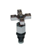
2 Position, 2 Way Normally Closed Poppet Type Manual Valve
Parker’s selection of 2-position, 2-way normally-closed manual poppet valves provide a low leak solution to simple 2-way manually operated circuits. These valves are capable of flows up to 49 lpm (13 gpm) and pressures as high as 210 bar (3000 psi). Parker’s 2-position, 2-way normally-closed manual poppet valves are available with knob, stem, lever, or lock pin manual controls in a normally-closed configurations and are ideal for on/off style applications, such as emergency lift/lower circuits or just simple actuation or motor control on a variety of machinery within the construction, material handling, or industrial markets.
Markets:
• Construction
• Material Handling
• Miscellaneous Industrial
• Miscellaneous Mobile
Features/Benefits:
• Low leak poppet design
• External parts zinc plated
Applications:
• On/off applications
• Emergency lower/actuate applications
Additional Technical Insight:
DL081 is a manually operated 8 GPM (30 LPM) check valve that is rated for 3000 psi (210 Bar) and has leakage rates of less than 5 drops per minute. In the unactuated state oil at port 2 is prevented from exiting port 1. Once the valve is actuated, oil is allowed to pass from port 2 to port 1. Back pressures on port 1 greater than 80 psi (5.5 Bar) will prevent the internal spring from closing the poppet, so care should be taken to ensure port 1 is plumbed back to the reservoir with minimum restriction. Knob, Stem, Lever, and Lock Pin actuators are standard options.
DL101 is a manually operated 13 GPM (49 LPM) check valve that is rated for 3500 psi (240 Bar) and has leakage rates of less than 5 drops per minute. In the unactuated state oil at port 2 is prevented from exiting port 1. Once the valve is actuated, oil is allowed to pass from port 2 to port 1. Back pressures on port 1 greater than 250 psi (17.3 Bar) will prevent the internal spring from closing the poppet, so care should be taken to ensure port 1 is plumbed back to the reservoir with minimum restriction. Knob and Stem actuators are standard options.
Parker’s DL081 and DL101 manual check valves are ideal for emergency lowering applications and for on-off applications where manual actuation is desired to allow flow to return to a reservoir with limited back pressure. -
3 Position, 4 Way Pull/Push to Shift Spool Type Manual Valve
DMH085 manual 4-way 3-position valves allow for directional control of bi-directional motors, double acting cylinders, and rotary actuators by pushing or pulling an integrated knob which is attached to a spool inside the cartridge. The spool is spring centered and available with multiple neutral position options including closed-center, float-center, tandem-center, and open-center. Multiple spool configurations provide design flexibility for use with fixed or variable displacement pumps, various actuator types, and different load holding approaches. Application engineers are available to help determine the best solution for your system. Typical applications include, hoists, material handling, construction, agriculture, oil and gas, machine tools, presses, forging, power units, grinders, mixers, drills and refuse. -
3 Way Rotary Type Manual Valve
DM103 valves are 3-way manually operated rotary spool type directional control valves. Knob, Finger-Knob and Lever actuators are available. Versions K, LD and FKD are 2-position valves that are actuated by turning the knob or lever a full 90 degrees. LN and FKN versions are 3-position valves which have a closed center condition and can be actuated by rotating the knob 45 degrees in either direction. All versions except K come standard with detents.
Parker’s DM103 series of manually operated valves can be applied as normally open or normally closed and can also be used as selectors. Typical applications include, hoists, material handling, construction, agriculture, oil and gas, machine tools, presses, forging, power units, grinders, mixers, drills and refuse. -
Direct Acting Sequence Valve
Parker’s family of direct acting sequence valves are fast acting and designed for sequenced applications with pressures up to 420 bar (6000 psi) and flows up to 56 lpm (15 gpm) in a variety of sizes. The selection of pressure adjustment styles and piloted or vented controls makes these valves an ideal solution for controlling multiple circuit sections that operate at different pressure settings. Normally-open and normally-closed valves are available in either 2 position 2-way or 2 position 3-way configurations. These direct acting sequence valves can be used within clamping circuits or high/low system applications within several industrial and mobile markets.
Markets:
• Agriculture
• Construction
• Material Handling
• Miscellaneous Industrial
• Miscellaneous Manufacturing
• Miscellaneous Mobile
Features & Benefits:
• Fast response
• Internal mechanical stops limiting spool travel
• Hardened, precision ground parts for durability
• All external parts zinc plated
• Adjustable, fixed, or tamper resistant adjustments available
Applications:
• Dump circuits
• High/low systems
• Sequencing applications
Additional Technical Insight:
Direct acting sequence valves are spool-type devices that allow multiple functions to operate in sequence without the need for solenoid valves, limit switches, or complex control systems. Parker’s B02, B04, and SV10 sequence valves provide design options for 2-position 2-way or 2-position 3-way sequencing with pilot signals and drains provided internally or externally. Externally drained versions are not sensitive to downstream pressure if they are drained to the tank. One or more sequence valves can be used in a circuit to allow multiple functions to operate in a specific order based on pressure. Normally closed and normally open versions are available to allow for design flexibility.
Parker’s B04H4, B04J4, and SV104 series of direct acting sequence valves are Externally Piloted and Externally Drained. The Normally Closed B04H4 is a 2-position 2-way valve that blocks flow in both directions until an external pilot supply pressure overcomes the sequencing setting. B04J4 and SV104 are Normally Open 2-position 2-way valves that allow bi-directional flow until the external pilot supply reaches the sequence setting. All three valves are insensitive to back pressure when their drain line is connected to tank.
Parker’s B04F3, B04G3, B04K4, and SV105 series of direct acting sequence valves are Externally Piloted and Internally Drained. The Normally Closed B04F3 and SV105 are 2-postion 2-way valves that prevent flow from passing from port 3 to 2 until an external pilot supply pressure overcomes the sequencing setting. Once the sequence pressure is reached the valve will open allowing flow from port 3 to 2. B04G3 is a 2-position 2-way Normally Open valve that allows flow from port 2 to 3 until the external pilot pressure reaches the sequence pressure blocking flow from 2 to 3. B04K4 is a 2-position 3-way normally open valve that allows bi-directional flow between ports 2 and 3 until the sequence pressure is met. Once the pilot pressure exceeds the set pressure, port 2 is blocked and flow is allowed from port 3 to port 4. The internal drain causes downstream pressure to be additive to the valves pressure setting, therefore it is most common for the downstream port to be connected to tank.
Parker’s B02E3F and B04E3 direct acting 2-position 3-way sequence valves are Internally Piloted and Internally Drained. Flow from port 2 to 1 is normally open until the pressure at port 1 exceeds the valves setting which closes port 3 and allows flow from port 1 to port 2.
Parker’s SV103 direct acting 2-position 3-way sequence valve is Internally Piloted and Externally Drained. Flow from port 1 to 2 is Normally Closed until the pressure at port 1 exceeds the sequence setting which allows flow from port 1 to 2. Port 3 is a dedicated spring chamber vent which makes the valve insensitive to downstream pressure at port 2.
Please contact Parker Hydraulic Cartridge Division if you have a sequencing application that requires higher flow rates. Pilot Operated Sequence Valves are capable of flows up to 42 GPM. Higher flows up to 130 GPM can be achieved with the use of logic elements and small pilot valves. -
4 Way Rotary Type Manual Valve
DM104 valves are 4-way manually operated rotary spool type directional control valves. Knob, Finger Knob and lever actuators are available. Versions K, LD and FKD are 2-position valves that are actuated by turning the knob or lever a full 90 degrees. LN and FKN versions are 3-position valves which have a closed center condition and can be actuated by rotating the knob 45 degrees in either direction. All versions except K come standard with detents.
Parker’s DM104 series of manually operated valves are perfect for many 4-way directional control applications where manual operation is required. Typical applications include, hoists, material handling, construction, agriculture, oil and gas, machine tools, presses, forging, power units, grinders, mixers, drills and refuse. -
Check Valve with Thermal Relief
Parker’s D04F2 is a poppet style check valve capable of flows up to 40 gallons per minute. Integral to this valve is a thermal relief valve that protects the circuit from expansion of the hydraulic fluid due to temperature rise. This relief will also act to relieve pressure spikes due to shock. Designers can use Parker supplied pilot spools to create a pilot operated check valve with the thermal relief functions. Common industries where these valve are found:
Forestry
Aerial Lift
Crane
Construction Equipment
Industrial Equipment -
Pressure Compensated Priority Flow Control Valves
Priority style pressure compensator flow control valves maintain constant priority flow to one leg of a circuit regardless of any changes in load or inlet pressure. Once the priority flow is satisfied, any excess flow may be used in other parts of the circuit.
The valve consists of a control orifice housed within a spring biased compensator spool. This orifice may be fixed or adjustable. The priority port is normally open while the bypass port is normally closed. As flow enters the inlet port of the cartridge, it passes through the control orifice. A pressure differential is created across the compensator spool. If the inlet flow exceeds the setting of the valve, the force produced by this pressure differential exceeds the spring force and shifts the compensator spool; opening up the bypass port, and bypassing the excess flow. If the load pressure at the bypass port is greater than the load pressure at the priority port, the compensator spool will further shift restricting the priority flow to that of the valve setting. However, caution should be taken if the priority gets blocked so that no flow can pass through the control orifice, the compensator spool will shift, blocking the bypass port and allowing inlet pressure to go to full system relief pressure. It is common to place an external relief valve downstream of the priority flow port to prevent a no flow condition.
Parker offers four styles of Pressure Compensated Priority Flow Controls ranging from 4 to 24 gallons per minute. Parker’s offering is as follows:
J02D3 - 4 gpm rated flow, 6000 psi, and is available with adjustment styles of Screw adjust, Knob adjust, and a Tamper resistant cap. Customers can request specific flow settings. Buna and Fluorocarbon seals available.
FP101 - 8 gpm rated flow with 15 gpm max inlet, 3500 psi, with adjustment styles of Fixed, Knob, and Screw. Nitrile and Fluorocarbon seals available.
J04D3 - 12 gpm rated flow, 6000 psi, and is available with adjustment styles of Screw, Knob, and Tamper Resistant cap. Customers can request specific flow settings. Nitrile and Fluorocarbon seals available.
J1A125 - 24 gpm rated flow, 5000 psi, and is available with adjustments styles of Screw, Knob, and Tamper Resistant. Customers can request specific flow settings. Nitrile and Fluorocarbon seals available.
Pressure compensated priority flow control valves are typically used in meter-in type circuits like steering (mobile equipment) or actuator speed control (industrial equipment) where a fixed displacement pump is being used. -
Pressure Compensators/Control Elements
Inlet flow (upstream of the orifice or flow control valve) is split with one portion going to the compensator port inlet, the other portion passes through the orifice, or flow control valve, to the supply port. As pressure drop across the orifice reaches the selected compensator pressure drop, the higher pressure (pre-orifice) starts to shift the compensator spool into a throttling position. The valve works to maintain a constant pressure drop across the orifice. Using this type of valve allows greater flexibility in design and flows as these valves can flow as much as 40 gallons per minute.
Compensator valves are used in circuits where a constant flow is desired regardless of upstream or downstream loads. As the pressure downstream of the compensator increases, the valve is forced open to maintain the constant pressure drop across the fixed, or adjustable, orifice. Conversely, if the pressure increases upstream of the orifice, the compensator valve will be forced closed to maintain the constant pressure drop across the orifice.
Parker offers two sizes of restrictive type of pressure compensators ranging in flows from 10 gallons per minute to 40 gallons per minute, and pressures up to 3500 psi.
FCR101 - 10 gpm rated flow (38 lpm), 3500 psi. Differential pressure ranges of 40, 80, and 160 psi and is available with Nitrile or Fluorocarbon seals.
FCR161F - 40 gpm rated flow (150 lpm), 3500 psi. Differential pressure ranges of 40 and 160 psi and is available with Nitrile or Fluorocarbon seals.
Pressure compensators can typically be found in applications such as conveyor circuits in saw mills, or lumber yards, steel mills, or cylinder control circuits in steel mills or foundries. -
Pressure Compensated Flow Control Valves
Parker offers a wide range of spool type restrictive pressure compensated flow controls to allow for speed control of motors, cylinders, and rotary actuators. Pressure compensation allows the flow devices to maintain a constant flow even with varying loads and inlet pressures. Tunable and fully adjustable versions are available with screw or knob adjusters that can be made tamper resistant with the addition of an optional cap.
FR101 is a tunable pressure compensated flow regulator which compensates for varying loads and pressures in one direction but in the other direction flow is metered across a fixed orifice but not compensated. In order to allow pressure compensated flow control in one direction and full free flow in the opposite direction, Parker offers an internal check valve in the tunable FC101 cartridge. Because both versions are tunable and not fully adjustable, the valve will need to be specified with the appropriate flow range for the application. Changes in flow rates are achieved by mechanically varying the spring force acting on a spool that has a fixed orifice and metering compensator.
J02E2, J04C2, and J04E2 are fully adjustable pressure compensated flow regulators. In the opposite flow direction they only meter through a fixed orifice and do not compensate. In order to achieve fully adjustable pressure compensated flow control while allowing reverse full flow, the FA101 includes an internal check valve to bypass the compensator and metering orifice.
Typical applications and industries include Accumulator Bleed-off, Motor Speed Control, Cylinder Speed Control, Bleed-Off Flow, Power Units, Oil and Gas, Material Handling, Construction, Drills, Presses, Mixers, Agriculture, Balers, Combines, etc. -
Needle Flow Control Valves
Needle valves offer economical solutions for applications that require basic adjustable control of hydraulic flow. The effective orifice size inside the valve is varied with screw or knob adjustments and the valve can be made tamper resistant with the addition of an optional cap. Shutoff can be achieved when the valve is adjusted completely closed. Once the adjustment is set, the valve acts as a fixed orifice. Like all fixed orifices, any changes in pressure will cause changes in flow. If constant flow is required regardless of system or load pressure, please consider Parker’s pressure compensated flow controls.
Parker’s J02A2, NVH081, NVH101, and J06A2 cartridges are basic 2-port needle valves with fine adjustment options available. The orifice will meter in both directions, but flow from port 2 to 1 is preferred. If unrestricted reverse flow is required, an additional check valve will need to be used with these needle valve versions.
Parker also offers J02B2, FV101, and FV102 needle valves with internal reverse free flow checks in order to reduce manifold size and component quantities. Typical applications and industries include Accumulator Bleed-off, Motor Speed Control, Cylinder Speed Control, Bleed-Off Flow, Power Units, Oil and Gas, Material Handling, Construction, Drills, Presses, Mixers, Agriculture, Balers, Combines, etc. -
Flow Divider/Combiner Valves
Each of Parker’s four flow divider/combiner versions can be used as a divider or combiner depending on the direction of flow. Two inter-locking spools allow for pressure compensated flow division and combination to be proportioned based on the selected ratio and flow range. When port 3 is supplied flow it is divided by a fixed ratio to work ports 2 and 4. For example, if a 50:50 ratio is selected half of the flow will exit port 2 and the other half will exit port 4. If the actuators have the same area or displacement they will operate at the same speed. If different actuator speeds are required, alternative ratios can be selected to supply different flows to each port. Ratios other than 50:50 can allow speed synchronization of two actuators that have different areas or displacements. The flow to each actuator port is proportional to the inlet flow based on the flow division ratio.
When used as a combiner, flow applied to ports 2 and 4 is combined and the total flow exits port 3. The flow from the combiner inlet ports is pressure compensated and the flow ratio determines how much flow is allowed from each port. Just like the divider mode, the combiner mode allows for actuator speed variation or synchronization.
Typical flow accuracy is +/- 10% between ports 2 and 4. When trying to synchronize 2 cylinders or motors, cross-port relief valves or balancing orifices can be used to help maintain tighter synchronization.
Parker’s FDC101, L04A3, L06A3 and L1A300 flow divider/combiners operate in the same manner with each having a different maximum flow and multiple standard ratios and flow ranges. Typical applications and industries include cylinder synchronization, motor synchronization, flow partitioning, transmission differentials, construction, oil and gas, material handling, military, grinders, mixers, drills, snow blowers, etc. -
Priority Pressure Compensators
Parker offers two styles of Priority Pressure Compensators, ranging in flows from 10 to 20 gallons per minute, and pressure capabilities of 3500 psi and 5500 psi. Flow through the external orifice (fixed or variable) enters the supply port and produces a pressure drop across the compensator spool. When the inlet pressure exceeds the initial setting of the valve, the force produced by the pressure differential across the spool exceeds the spring force and shifts the compensator spool to throttle, or restrict, the flow, thus maintaining constant flow through the priority port. The excess flow is bypassed out to the system to be used by another function, or back to the system reservoir. Flow out the regulated port must be maintained for bypass flow to continue. For this reason, common practice dictates a pressure control (relief) be installed in the priority line.
Parker offers the following styles of Priority Pressure Compensators:
FCP101 - Up to 10 gallons per minute priority flow rate (38 lpm), 15 gallon per minute maximum inlet flow (56 lpm), 3500 psi. Available with differential pressure settings of 40, 80, and 160 psi. Nitrile and Fluorocarbon seals available.
FCPH121 - Up to 20 gallons per minute priority flow rate (75 lpm), 25 gallons per minute maximum inlet flow (95 lpm), 5500 psi. Available with fixed (customer specified) or variable differential pressure settings. Adjustments are knob or screw adjust, with a tamper resistant cap available.
Priority Pressure Compensators are used where the design calls for constant flow to a particular segment of the circuit, regardless of upstream or downstream pressure (load) changes. A common application is for speed control on a conveying system. Should the load on the conveyor increase, the pressure increases at the compensator and the valve modulates to maintain the desired pressure differential across the valve. This modulation allows more flow to pass through the valve thus maintaining a constant desired speed. Conversely, should the load on the conveyor decrease, the opposite happens and the compensator modulates, restricting some flow to maintain the desired pressure differential, thus providing constant speed.
Parker Priority Pressure Compensators may be found in steering circuits, conveying systems, lift/lower systems in markets such as mobile/agricultural companies, steel or lumber mills, or off-highway mobile equipment. -
2-drogowy zawór elektromagnetyczny typu grzybkowego
2-drogowe grzybkowe zawory elektromagnetyczne firmy Parker mają sprawdzoną konstrukcję gwarantującą niskie przecieki wewnętrzne, gdy przepływ jest blokowany w jednym kierunku oraz zminimalizowany spadek ciśnienia w pozycji przepływu swobodnego. Zawory te mogą pracować w układach hydraulicznych o przepływach do 260 l/min i ciśnieniach do 350 bar w konfiguracjach: normalnie otwarty lub normalnie zamknięty. 2-drogowe grzybkowe zawory elektromagnetyczne firmy Parker są idealne do odciążania i utrzymywania obciążenia, gdy wymagane są niskie przecieki zapewnione przez konstrukcję typu grzybkowego, przeznaczone na rynki urządzeń mobilnych, przemysłowych lub produkcyjnych.
Rynki:
• Podnośniki osobowe
• Budownictwo
• Transport materiałów
• Przemysł
• Produkcja
• Urządzenia mobilne
Cechy i korzyści:
• Wymienne jednoczęściowe cewki o niskim poborze prądu
• Dostępny krótki czas reakcji
• Opcje sterowania ręcznego
• Kulisty grzybek zapewniający niskie przecieki
• Wszystkie części zewnętrzne ocynkowane
Zastosowania:
• Obwody odciążające
• Utrzymywanie obciążenia
• Układy podnoszenia
Dodatkowe informacje techniczne:
2-drogowe zawory grzybkowe firmy Parker to sterowane pośrednio zawory elektromagnetyczne o niskich przeciekach. Podobnie jak zawory zwrotne, zawory te blokują przepływ w jednym kierunku przy bardzo małych przeciekach (5 kropli na minutę lub mniej). Po aktywacji zawory te umożliwiają przepływ. Zawory te są zazwyczaj wybierane ze względu na ich niski stopień przecieków oraz możliwość stosowania do wyższych przepływów. Zawory grzybkowe są często stosowane razem z siłownikami jednostronnego działania lub w funkcji odciążania. Są one dostępne w wersjach normalnie zamkniętej i normalnie otwartej oraz w wersjach o krótkim czasie reakcji.
Dwudrogowe, dwupołożeniowe zawory grzybkowe firmy Parker składają się z grzybka głównego, grzybka pilotującego, sprężyny i cewki elektromagnesu.
Wersja normalnie zamknięta tych zaworów grzybkowych działa jako zawór zwrotny, gdy elektromagnes nie jest zasilany. Blokuje przepływ w jednym kierunku, umożliwiając przepływ w kierunku przeciwnym Po włączeniu zasilania cewki grzybek jest sterowany do pozycji otwartej (podnosi się) i umożliwia swobodny przepływ w uprzednio zablokowanym kierunku, zwykle w kierunku od strony bocznej zaworu do jego końcówki.
W przypadku wersji normalnie otwartej tych zaworów grzybkowych, po wyłączeniu zasilania cewki możliwy jest swobodny przepływ z bocznego przyłącza zaworu (przyłącze 2) do końcówki zaworu (przyłącze 1). Włączenie zasilania cewki powoduje przesunięcie grzybka i zablokowanie przepływu w kierunku 2 do 1.
Zasada działania: Normalnie zamknięty zawór grzybkowy jest utrzymywany w gnieździe przez sprężynę, blokując drenaż pilota. Dzięki temu ciśnienie na przyłączu wlotowym (przyłącze 2) może utrzymać grzybek w gnieździe, uniemożliwiając przepływ przez zawór (od przyłącza 2 do przyłącza 1).
Jeśli ciśnienie na końcówce naboju (przyłącze 1) jest wystarczające, aby pokonać siłę sprężyny i wypchnąć grzybek z gniazda, możliwy będzie przepływ w kierunku 1 do 2. Po włączeniu zasilania cewki grzybek pilotujący jest podnoszony z gniazda, uwalniając ciśnienie wewnątrz grzybka do przyłącza 1. Powoduje to nierównowagę ciśnienia na grzybku głównym, a w konsekwencji jego podniesienie i umożliwienie przepływu z boku na końcówkę (z 2 do 1). Ponieważ zawory te są sterowane pośrednio, konieczna jest minimalna różnica ciśnień (25–50 psi) oraz przepływ między przyłączami 2 i 1, aby pokonać siłę sprężyny i podnieść grzybek.
Pilot zaworu normalnie otwartego jest utrzymywany poza gniazdem przez siłę sprężyny. Pilot jest drenowany do przyłącza 1, powodując niezrównoważenie ciśnienia, które sprawia, że grzybek główny się porusza. Ta różnica powoduje podniesienie grzybka, umożliwiając przepływ z boku zaworu na jego końcówkę (z 2 do 1). Ponieważ zawory grzybkowe są sterowane pośrednio, minimalna różnica ciśnienia (25–50 psi) między przyłączami 2 i 1 powoduje pokonanie siły sprężyny i przemieszczenie pilota zaworu i grzybka głównego do ich gniazd, blokując w ten sposób przepływ z przyłącza 2 do 1. Jeśli występuje ciśnienie na końcówce naboju (przyłącze 1), pokonuje ono siłę sprężyny i siłę elektromagnesu, wypychając grzybek z gniazda i umożliwiając ograniczony przepływ przez nabój (z 1 do 2). -
2 Way Spool Type Solenoid Valve
Parker’s readily available Winners Circle line includes common cavity C08-2 and C10-2 direct acting 2-way, 2-position spool valves.
The DSL082 and DSL102 series of valves are rated for 3600 psi (250 bar.) For applications that require pressures up to 5000 PSI (350 BAR,) Parker also offers the DSH082 and DSH102 valve series. All versions are available normally-open, or normally-closed and can be provided with optional Pull & Release or Push & Twist manual overrides. Direct acting spool valves are fast to respond to coil voltage and will block flow in both directions. Some leakage will be present due to spool clearances so please consider Parker’s 2-way Poppet Valves if leakage less than 5 drops per minute is required. Even though flow is bi-direction, due to flow forces, the preferred flow path is from the side of the cartridge (port 2) to the nose (port 1.)
In addition to the Winners Circle product, Parker also offers the direct acting 2-way, 2-position GS02 series of valves with flows up to 4 GPM (15 LPM) and pressures as high as 5000 PSI. GS02 22 is normally-closed and GS02 27 is normally-open. Both versions are available with optional Push and Release, or Detented Screw-type manual overrides.
Parker also offers a 20 GPM (75 LPM) 3000 PSI (210 BAR) direct acting 2-way, 2-position spool valve for applications that require higher flow rates. The DS162 cartridge valve is available normally-open or normally-closed and comes standard with a Push and Release manual override.
Combined with Parker’s wide range of Coil options which include AC and DC voltages and extensive termination options, the 2-way direct acting spool valve offering allows for application specific solutions in the most demanding applications and markets including: Power Units, Oil and Gas, Material Handling, Construction, Drills, Presses, Mixers, Agriculture, Balers, Combines, etc. -
3 Way Spool Type Solenoid Valve
Parker’s readily available Winners Circle line includes common cavity C08-2 and C10-2 direct acting 3-way, 2-position spool valves capable of flows up to 8 GPM (30 LPM.) The DSL083 and DSL103 series of valves are rated for 3600 psi (250 bar.) For applications that require pressures up to 5000 PSI (350 BAR,) Parker also offers the DSH083 and DSH103 valve series. Normally-open, normally-closed, and selector spool variations are available for all versions and each can be provided with optional Pull & Release or Push & Twist manual overrides. Direct acting spool valves are fast to respond to coil voltage and will allow flow passage between 2 ports while blocking the remaining port. Some leakage will be present due to spool clearances.
Parker also offers a 15 GPM (57 LPM) 3000 PSI (210 BAR) direct acting 3-way, 2-position spool valve for applications that require higher flow rates. The DS163 cartridge valve is available normally-open or normally-closed, and can be used as a selector. A Push and Release manual override is standard.
Combined with Parker’s wide range of Coil options which include AC and DC voltages and extensive termination options, the 3-way direct acting spool valve offering allows for application specific solutions in the most demanding applications and markets including: Power Units, Oil and Gas, Material Handling, Construction, Drills, Presses, Mixers, Agriculture, Balers, Combines, Single Acting Cylinder Control, Uni-Direction Motor Control, Circuit Selectors, etc. -
4 Way 2 Position Spool Type Solenoid Valve
Parker’s readily available Winners Circle line includes common cavity C08-2 and C10-2 direct acting 4-way, 2-position spool valves capable of flows up to 8 GPM (30 LPM.) The DSL084 and DSL104 series of valves are rated for 3600 psi (250 bar.) For applications that require pressures up to 5000 PSI (350 BAR,) Parker also offers the DSH084 and DSH104 valve series. Multiple spool variations are available for application flexibility and all versions can be provided with optional Pull & Release or Push & Twist manual overrides. Direct acting spool valves are fast to respond to coil voltage and can quickly re-direct or block flow to actuator ports. Some leakage will be present due to spool clearances.
In addition to the Winners Circle product, Parker also offers a direct acting 4-way, 2-position GS02 series capable of flows up to 5 GPM (19 LPM) and pressures as high as 5000 PSI. GS02 42 comes with one standard spool configuration and optional Push and Release, or Detented Screw-type manual overrides are available.
Parker also offers a 30 GPM (114 LPM) 5000 PSI (350 BAR) direct acting 4-way, 2-position spool valve for applications that require higher flow rates. The DSH164 cartridge valve comes with one standard spool configuration and manual overrides are not available as a standard option.
Combined with Parker’s wide range of Coil options which include AC and DC voltages and extensive termination options, the 4-way direct acting spool valve offering allows for application specific solutions in the most demanding applications and markets including: Power Units, Oil and Gas, Material Handling, Construction, Drills, Presses, Mixers, Agriculture, Balers, Combines, Double Acting Cylinder Control, Bi-Direction Motor Control, Circuit Selectors, etc. -
3 Way Pilot Operated Directional Control Valves
Parker’s three way pilot operated spool valves are used to direct flow alternately from either side of a closed loop transmission for cooling or filtering. With flow ranging from 10 gpm to 24 gpm, and pressures up to 5000 psi, these valves are a versatile solution to many hydrostatic applications.
Parkers DH103 series valve is rated for 10 gpm at 3500 psi. This 3 ported valve is available in both normally open and normally closed orientation. Two versions of the normally open series are available. The DH103A series in its neutral (deactivated) position allow Port 3 open to Port 2, with port 4 blocked. Pilot pressure at Port 1 shifts the spool blocking Port 2, allowing Port 3 to be open to Port 4. The DH103A valve is a vent to atmosphere valve allowing pressure equalization in the spring chamber.
Parker’s DH103B configuration is a normally closed version of the valve. In its neutral (deactivated) orientation, Port 2 is blocked while Port 4 is open to Port 3. When a pilot signal is applied to Port 1, the spool is shifted blocking Port 4, allowing Port 3 to be open to Port 2. Unlike DH103A, the spring chamber is vented to Port 4. Care must be taken to be aware of back pressure in Port 4 being additive to the spring setting.
Parker’s DH103C series is a normally open version, operating like the DH103A series, with the exception of the vented spring chamber.
The DH103 series of valves are available with three switching pressures (40 psi, 80 psi, 160 psi) and Nitrile or Fluorcarbon seals.
Parker’s N04A4 and N04B4 are higher flow versions of the DH103B and DH103C valves. The N04A4 series operation in its neutral (deactivated) position allow Port 3 to be open to Port 4, with Port 2 blocked. When a pilot signal is activated at Port 1, the spool shifts against the spring allowing Port 3 to be open to Port 2, with Port 4 blocked. The spring chamber is vented to Port 4 so care needs to be taken with back pressure at Port 4 additive to the spring setting.
Parker’s N04B4 series operation in its neutral (deactivated) position allows Port 3 to be open to Port 2, with Port 4 blocked. When a pilot signal is activated at Port 1, the spool shifts against the spring allowing Port 3 to be open to Port 4, blocking Port 2. The spring chamber is vented to Port 4 so care needs to be taken with back pressure at Port 4 additive to the spring setting.
Parker’s N04 series of Pilot Operated Directional Valves are available with switching pressures of 73 psi and 145 psi, and are available with either Nitrile or Fluorocarbon seals. -
5 Way/2 Position Pilot Operated Directional Control Valves
N5 cartridge valves from Parker provide design flexibility for high pressure and high flow applications because they are actually 5-ported cartridges. Each version has 3 work ports, 1 Main pilot port, and one spring chamber vent that can sometimes be used as a second pilot / sense port. Each cartridge contains a spool that is offset by a spring to allow a non-piloted flow configuration. Once pilot pressure is applied to port 1, the spool shifts against the spring creating a second flow configuration. Multiple spool configurations, transition types, and switching pressures are available to cover a wide range of applications.
N5A125 and N5A300 cartridge valves have an open transition which connects all 3 work ports together during the shifting of the spool. Both versions operate in the same manner with the key difference being flow rating. The N5A125 is rated for 42 GPM (160 LPM) and the N5A300 is rated for 105 GPM (400 LPM.) They can be used as normally-open, normally-closed and selector directional control valves and in a wide range of pressure and/or flow control circuits. The 5th port spring chamber can be vented to tank or used as a sensing port for applications that require high flow pressure or flow control. Pressure compensation, priority flow control, pressure reducing, pressure relieving, and pressure sequencing are just a few of the applications for these extremely versatile cartridge valves.
N5B125 and N5B300 have the same respective flow ratings and operate in the same manner as the respective N5A125 and N5A300. The key difference is that N5B cartridges have a closed condition transition. Please contact your Parker Application Engineer for assistance selecting the best transition condition for your application.
N5C and N5D are similar in their operation to N5A and N5B cartridges but without the transition conditions and with either all work ports blocked or all work ports open. N5C125 and N5C300 cartridges have spools that are spring offset to a condition where all 3 work ports are open. Once pilot pressure is applied to port 1, all 3 work ports are blocked. N5D125 and N5D300 valves are spring offset to an all ports blocked condition. Once pilot pressure is applied, the spool shifts and all ports are connected together. Flow ratings for both size 125 styles is 42 GPM (160 LPM) and the size 300 styles are rated for 105 GPM (400 LPM.)
Parker’s N5 high flow 3-way 2-position control valve offering allows for application specific solutions in the most demanding applications and markets including: Power Units, Oil and Gas, Material Handling, Construction, Drills, Presses, Mixers, Agriculture, Balers, Combines, Priority Steering, Priority Braking, High Flow Pressure Compensation, etc. -
2 Way Pilot Operated Directional Control Valves
Parker’s R04* series of directional valves are available both normally-open and normally-closed. Flow ranges up to 26 gpm and pressure rating of 6000 psi, these valves are used as a switching valve by sensing pressure in other parts of the circuit.
The R04*3 series valve is a 2 way, 2 position valve that is 3 ported. With port one (nose) of the valve the pilot port, main flow goes through ports 2 and 3. The spring chamber is ported to port three so care needs to be taken making sure this is the low pressure side of the circuit.
When a pilot signal is given at port one, pressure acts upon the spool lifting it against the spring and closing flow from port two to port three. Spring chamber is vented internally out port three. When the pilot signal is removed, the spring acts upon the spool forcing it open to allow flow from ports two to three. Switching pressures of 5 bar and 10 bar are available. This valve is also available in a normally closed configuration.
The R04*4 series valve is a 2 way, 2 position valve that is 4 ported. Like the R04*3 series of valves, this valve received the pilot signal at port 1, shifting the valve against the spring and closing flow from port two to port three. A fourth port is connected to the spring chamber allowing the oil to vent independently of pressure at port three.
The R04 series of valve are used as a high flow directional control valve or unloader valve. Typical markets include, but are not limited to: Aerial lift, fork lift, off-road earth moving contruction equipment, industrial special machinery, conveying systems. -
Motor Control Valves
Load Holding, Hose Break and Overrunning Load Protection can be easily achieved with Parkers Low-Speed-High-Torque motors with the use of direct flange mounted MMB counterbalance packages. Space saving and plumbing reduction can be achieved when used with Parker TB, TE, TF, and TG motors. Both motor control packages are available with two pilot ratio options, and can be supplied vented, non-vented and with or without a motor brake release port. Superior counterbalance functionality is accomplished with the use of single or double MHC series load and motor control valves.
Parker’s offering of motor mounted counterbalance control valves allow design flexibility in the most demanding applications and markets including and not limited to: Refuse, Oil and Gas, Material Handling, Construction, Drills, Presses, Mixers, Agriculture, Balers, Combines, Load Holding, Hose Break Protection, Overrunning Load Control, Hydrostatic Drives, etc. -
Standard Pilot Vented Load Control Valves
Parker’s counterbalance, or load control, valves are available either vented, or non-vented style. The vented valves are available in flow ranges from 5 gallons per minute up to 48 gallons per minute, and pressures up to 5000 psi.
Typical uses of these valves are in applications where:
• Loads are lowered and a smooth operation is required to prevent a runaway condition
• Loads are handled using a cylinder operating in an over center condition
• Load drift needs to be eliminated due to control valve spool leakage
Sizing a counterbalance valve needs care in that the flow required is usually higher than system pump flow, as in the case with a cylinder application (retract flow could be twice the system flow). Oversizing the valve could cause instability. When the pressure setting is critical, a vented load control is preferred. Pressure in the spring chamber of the valve is vented to atmosphere and therefore independent of any back pressure from the tank line.
The pilot ratio is the ratio of the pilot area versus the differential area poppet. Thus, the higher the pilot ratio, the less pressure that is needed to assist the load pressure in unseating the poppet. This means there is less restriction to the overrunning load, resulting in less horsepower required and more control of the load. So higher pilot ratio equates to less restriction to the overrunning load, less control and less horsepower required. Lower ratio equates to more restriction to the overrunning load, more control and more horsepower required. The pilot ratio decision is one of Horsepower versus Control. For reference the most popular ratio is 6:1.
Parker offers counterbalance valves with adjustable and non-adjustable pressure settings. Non-adjustable, or shimmed version, is recommended for most applications as it prevents tampering or improper adjustment by uneducated users. -
Spool Type Logic Element
Spool type logic elements offered by Parker come in four basic variations with multiple sizes for each variation. Different sizes within each variation perform the same, but the larger the size (“_ _”) the more flow the valve is capable of passing. The advantage of using logic element technology is that high flows can be controlled using smaller pilot devices which can lead to more compact and efficient systems. Spool-type logic elements are typically used to control virtually any pressure or flow function since the spool is allowed to modulate. However, spool valves have clearances, so Parker also offers Poppet-Type logic elements for high flow 2-way, 2-position low leak requirements.
The first step to applying logic elements is to determine if the application requires direction, pressure, or flow control. Direction control is typically the simplest due to the fact logic elements are only 2-way devices that can be internally or externally piloted. If pressure or flow control is desired, designers have flexible options that can be implemented by selecting from four basic types of spool-type logic elements. The four types below are grouped together based on whether the valve is normally-open or normally-closed, and internally or externally piloted.
Type 1: _ _SLC2-A and R_ _E3 series are normally closed, external pilot to close cartridges that flow from port 1 to port 2. This simply means that the spool normally blocks flow from port 1 to port 2 due to the internal bias spring. If no external pilot source is applied to the bias spring chamber, via port 3, then flow will pass from port 1 to port 2 at the bias spring pressure setting. When pilot pressure is applied to port 3 it becomes additive to the bias spring setting. Pilot pressure at port 3 needs to be supplied and/or controlled from an external source. Typical high flow functions for these logic elements include pressure reliefs, sequence valves, priority compensation, unloading and load-sense unloading.
Type 2: _ _SLC2-B and R_ _F3 series are identical to Type 1, with the exception of an orifice drilled in the spool allowing pressure from port 1 into the bias spring chamber and port 3, thus providing an internal pilot supply.
Type 3: _ _SLC3-A and R_ _H3 series are normally open, external pilot to open cartridges that flow from port 2 to port 1. This simply means that the spool normally allows flow from port 2 to port 1. If no external pilot source is applied to the bias spring chamber, via port 3, flow from port 2 to port 1 will begin to meter and restrict flow at the bias spring pressure setting. When pressure is applied to port 3 it becomes additive to the spring setting helping to hold the valve open. Pilot pressure at port 3 needs to be supplied and controlled from an external source. Typical high flow functions for these logic elements include restrictive flow control, pressure compensation, and pressure reducing.
Type 4: _ _SLC3-B and R_ _G3 series are identical to Type 3, with the exception of an orifice drilled in the spool allowing pressure from port 1 into the bias spring chamber and port 3, thus providing an internal pilot supply.
Parker’s extensive high flow spool-type logic elements allow for application specific solutions in the most demanding applications and markets including: Power Units, Oil and Gas, Material Handling, Construction, Drills, Presses, Mixers, Agriculture, Balers, Combines, Priority Steering, Priority Braking, High Flow Pressure Compensation, Fixed Pump Unloading, Load-Sense Unloading, Priority Flow Control, etc. -
Poppet Type Logic Element
Parker’s logic valves offer system designers a versatile range of screw-in elements that, when used in the proper combinations, can provide flexible design solutions for many common cartridge valve applications. They offer system designers the advantage of applying cartridge valve technology in applications where the flow and pressure conditions may exceed the limits of typical cartridge valves. Logic valves are essentially high flow poppet or spool elements that are controlled by small pilot devices. They can be used to control flow, pressure, or direction, and when applied in the proper arrangements, can perform multi-task control functions. Parker’s logic valves offer system designers alternative products that can help reduce the size, cost, and complexity of integrated manifold systems.
Poppet type logic valves are 3 ported, 2-way on/off valves that switch flow between port 1 and port 2. The poppet’s on/off action is operated by controlling pilot oil at port 3 of the valve. A small low flow solenoid or pilot valve is an ideal control for this purpose. Parker offers vent-to open and pilot-to-close style poppet logic valves.
Note: Poppet logic valves are an unbalanced 2:1 ratio poppet design. The opening and closing of the poppet is dependent on the force balances on the areas of the poppet at port 1, port 2, and port 3.
Vent-to-open logic valves:
Vent-to-open logic valves are primarily used for unidirectional flow switching applications. The poppet in the vent-to-open logic valve is spring biased to the closed condition. The pilot oil source that operates the logic element is generated internally by direct pressure from either work port 1 or 2, depending on the option chosen. Venting the pilot oil at port 3 allows the valve to open and pass flow between port 1 and port 2 at the bias spring setting. Blocking the pilot at port 3 causes the valve to close. When closed, the 2:1 ratio poppet design provides a positive low leak seal. Because the pilot source is generated internally within the valve, vent-to-open logic valves are best suited for uni-directional applications.
Parker’s 16SLC1-C Vent-to-open logic element is a size 16 valve capable of up to 50 gpm, 3500 psi. Standard spring settings of 50, 75, 100, and 150 psi are available. Manufactured with hardened, precision ground parts for durability, the 16SLC1-C is only available with Polyurethane seals only.
Pilot-to-close logic valve:
Pilot-to-close logic elements are primarily used for bidirectional flow switching applications. The poppet in the pilot-to-close logic valve is spring biased to the closed condition. With no pilot signal at port 3, the valve will open allowing flow in either direction between work ports 1 and 2 once pressure at one of the work ports reaches the biased spring setting. Appling a sufficient externally generated pilot force to port 3 of the valve closes the poppet creating a low leak seal between port 1 and port 2.
2-way, 3-way, and 4-way Directional Control:
Poppet logic valves are typically used to perform high flow directional switching operations using small low power pilot valves to control the sequence of the directional operation.
• A single logic valve can be used to control 2-way, on/off switching.
• Multiple elements in a bridge arrangement can control 3-way or 4-way directional switching.
• Since each logic valve is individually controlled, the timing, sequence, and overlap of directional functions can be controlled very precisely.
• Uni-directional or bi-directional flow can be achieved, depending on the valve selected.
• Flows in excess of 80 gpm can be controlled through a single logic element, and more than one logic valve can be used in parallel to control flow in excess of the rated flow of a single element.
• Poppet construction provides a low leak directional control.
Parker offers a wide variety of pilot-to-close logic elements ranging from 15 gpm to 80 gpm, 3500 psi. Spring ranges of 50, 75, 100, and 150 psi are available. Manufactured with hardened, precision ground parts for durability, these valve are available with Polyurethane seals only.
Common applications for logic elements are directional control valves, creating 2 way, 3 way, and 4 way valves, usually using a solenoid operated cartridge valve. Bridge circuits capable of up to 80 gpm can be controlled with a size 10, low flow directional cartridge valve. Also common are pressure and flow control circuits.
These valves can be found in all markets but most commonly used in mobile construction equipment, aerial devices, cranes, and excavation equipment. Applications include, but are not limited to, boom extension/retraction, outrigger control, winch control, conveying, steering, and auger control. -
Standard Pilot Assisted Load Control Valves
Counterbalance valves are devices used to control cylinder and motor loads helping to restrict overrunning loads, assist with controlling speed and position for varying loads, and they are also used as load holding devices with built in thermal relieving functionality. Standard counterbalance valves are pilot operated devices that allow free flow in one direction and restricted flow in the opposite direction. The load is held in place until the counterbalance setting is overcome by sufficient pressure generated by the pump, thermal expansion, or from external forces acting on the actuator. Once the pressure falls below the required setting, the valve closes and holds the load in place. In order to save horsepower, pilot pressure assists in the opening of the valve allowing the load to be controlled with a lower than load induced pressure as long as the available pilot pressure is greater than the ratio between the valve setting and the selectable pilot ratio. Standard counterbalance valves are non-vented meaning the control spring chamber is connected to the valve outlet which will cause any downstream pressure to be additive the valves pressure setting. If excessive downstream pressure may be present or if the counterbalance pressure setting is critical, Parker also offers several series of externally vented counterbalance valves.
Parker’s CB101, MHC-010-S, MHC-022-S, and E2 series of counterbalance valves are all standard non-vented load and motor control valves. Each series has multiple pilot ratio options, adjustment styles, and available pressure ranges. They can also be supplied with fixed factory settings, or with tamper proof caps. Typically higher pilot ratios are used for simple load holding applications where the moving load is controlled by external means and the main purpose of the counterbalance is to hold the load in position when not being operated, and to provide thermal and hose-break protection. Lower pilot ratios are typically used to assist in applications where cylinder or motor speed and positioning needs to be controlled with varying loads.
MHB-015-L and MHB-030-L are counterbalance valve assemblies consisting of an in-line or gasket mounted body and one or two counterbalance valves. In-line mounted bodies can allow the counterbalances to be placed remotely on the machine and plumbed from a distance or directly to an actuator using hose, pipe, or tubing. Gasket mounted version reduce required plumbing and also leak points by allowing the counterbalances to be mounted directly on the motor, cylinder, or rotary actuator.
Parker’s extensive line of counterbalance load and motor control valves allow design flexibility in the most demanding applications and markets including and not limited to: Power Units, Refuse, Oil and Gas, Material Handling, Construction, Drills, Presses, Mixers, Agriculture, Balers, Combines, Load Holding, Hose Break Protection, Overrunning load control, etc. -
3 Way Flow Control Proportional Valves
Parker’s proportional flow control valves provide electronically variable flow control. Varying coil current will create a proportional flow out to an actuator allowing control of speed, acceleration, and deceleration. AC and DC coil options are available, along with a wide range of connection types. Current Controlled Pulse Width Modulation (PWM) valve drivers are preferred as they adjust for variations in coil temperature and also provide the ability to apply a dither frequency.
Priority Bypass is the last type of proportional flow control manufactured by Parker. Two sizes are available and the largest version is capable of flows up to 20 GPM (75 LPM.) Priority bypass flow controls are 3-way spool-type valves that consist of an inlet port, a priority port, and a bypass port. When no current is applied to the coil, all inlet flow exits the bypass port. As current is increased the spool shifts allowing a proportional amount of pressure compensated flow to the priority port while bypassing any remaining flow to the bypass port. Bypass flow is not allowed unless the priority ports has achieved the commanded proportional flow rate based on the input current. This allows for a priority of flow to one part of a circuit regardless of varying load conditions in both parts of the circuit. Typical priority applications include braking and steering.
Combined with Parker’s wide range of Coil options, the extensive proportional flow control offering allows for application specific solutions in the most demanding applications and markets including: Power Units, Oil and Gas, Material Handling, Construction, Drills, Presses, Mixers, Agriculture, Balers, Combines, Double Acting Cylinder Control, Bi-Direction Motor Control, Circuit Selectors, Skid-Steers, etc. -
Pressure Reducing Proportional Valves
Parker’s proportional pressure reducing valves provide electronically variable reduced pressure to protect system components and assist in force and torque control. Pressure reducing relieving valves are of spool-type design and consist of an inlet port, a reduced pressure port, and a tank port. Varying coil current will create a proportionally lower output pressure in the reduced pressure port when supplied a higher pressure at the inlet port. When no current is applied the reduced pressure port is vented to tank and the inlet port is blocked by the spool. Once current is applied the spool shifts and meters flow from the inlet port to the reduced pressure port and maintains a constant pressure at the reduced pressure port. Higher current results in a higher reduced pressure. The reduced port pressure is relieved to tank if it exceeds the valves input command pressure. AC and DC coil options are available, along with a wide range of connection types. Current Controlled Pulse Width Modulation (PWM) valve drivers are preferred as they adjust for variations in coil temperature and also provide the ability to apply a dither frequency.
Combined with Parker’s wide range of Coil options, proportional pressure reducing / relieving valves allow for application specific solutions in the most demanding applications and markets including: Power Units, Oil and Gas, Material Handling, Construction, Drills, Presses, Mixers, Agriculture, Balers, Combines, Double Acting Cylinder Control, Bi-Direction Motor Control, Circuit Selectors, Skid-Steers, etc. -
Pressure Compensated Proportional Poppet Valves
Parker Hydraulic Cartridge Systems Division combines Parker’s precision ground poppet and SuperCoil technology with a newly patented integral compensator design, bringing you a flow control product with best in class repeatability and a truly exceptional level of control.
In conditions of varying load, the FAPC series maintains predictable and repeatable performance through the introduction of our new fully integrated compensator. Built directly into the FAPC series valves, the innovative new compensator maintains a tight seal for load holding without any requirement for additional sealing. When open, the compensator responds to changing load conditions independently. With no seal friction to overcome, the FAPC valve maintains the repeatable and predictable performance customers can rely on. This additional feature eliminates the need for complex programming algorithms, and any requirement for an external compensator to improve the operator’s control.
• Excellent metering capability and control throughout the full flow range
• Reduced drift
• Low leak control (less than 5 dpm)
• Modular solution to applied problem
• Low leak compensator, requiring no additional seals, results in very low hysteresis (< 10%)
• Maintains constant flow regardless of load condition
• Patented integrated low leak compensator
How it works:
The FAPC utilizes a control current to proportionally raise and lower a poppet creating a variable orifice allowing flow to pass through from the inlet to the outlet. There is also a low leak integral compensator that responds to load changes in the hydraulic circuit by varying the outlet orifice, metering the flow rate that can be passed through and maintaining constant flow independent of load conditions.
The fully compensated FAPC is rated to flows up to 115 LPM (22 GPM).
Common markets and applications include the aerial markets (boom raise/lower), fork lift (lift/lower) and vehicle lift. -
Proportional Poppet Valves
Parker Hydraulic Cartridge Systems Division combines Parker’s precision ground poppet and SuperCoil technology with a newly patented integral compensator design, bringing you a flow control product with best in class repeatability and a truly exceptional level of control.
Parker’s innovative new flow control product is available in a non-compensated (FAP) format. The FAP series offers repeatable and accurate operation throughout the full control range of the valve. Available in flow ranges from 7 gpm to 31 gpm and pressures up to 3000 psi, the FAP proportional flow control poppet valves come both normally open and normally closed. The FAP utilizes a control current to proportionally raise and lower a poppet creating a variable orifice allowing flow to pass through from the inlet to the outlet.
• Excellent metering capability and control throughout the full flow range
• Reduced drift
• Low leak control (less than 5 dpm)
• Modular solution to applied problem
• Improved control throughout the control range
Common markets and applications include the aerial markets (boom raise/lower), fork lift (lift/lower) and vehicle lift. -
Pressure Relieving Proportional Valve
Parker offers direct and pilot operated proportional relief valves. Two styles are available; increasing pressure with increasing current, and decreasing pressure with increasing current. All styles offered normally opened or normally closed.
Normally Closed Proportional Relief Valve
Normally closed proportional relief valves are used to electronically control the system pressure. These valves are ideal for circuits with varying system pressures demands. A small flow pilot version of the normally closed proportional relief is also offered for piloting a larger logic element or vented relief valve. The normally closed relief defaults to a maximum pressure setting (i.e. 3000 psi) when there is no current applied.
OPERATION - With the solenoid coil de-energized, the pilot dart is held closed by the spring. As current is applied to the coil, the pilot dart is moved creating less restriction of the pilot flow. As this restriction is reduced with the increasing current, the pressure setting also decreases. Once a constant electronic signal is given, the pilot dart is held in a given position, holding the pressure setting. This is maintained by the balance between the electronic spring force and the inlet pressure.
Normally Open Proportional Relief Valve
Normally open proportional relief valves are used to electronically control the system pressure. These valves are ideal for circuits with varying system pressure demands. A small flow pilot version of the normally open proportional relief is also offered for piloting a larger logic element or vented relief valve. The normally open relief defaults to minimum system pressure (i.e. 150 psi) when there is no current applied. Normally closed versions are also available upon request.
OPERATION - With the solenoid coil de-energized, the pilot dart is held open by the spring. This allows the main spool to open at minimum pressure 10.4 Bar (150 psi). As current is applied to the coil, the pilot dart is moved towards the pilot seat restricting pilot flow. This restriction raises the effective pressure setting of the valve. Once a constant electronic signal is given, the pilot dart is held in a given position, holding the pressure setting. This is maintained by a balance between electronic spring force and inlet pressure. As the electronic signal is reduced, the pilot dart is moved away from the pilot seat. This lowers the effective pressure setting of the valve.
Parker’s normally open series of Proportional Relief Valves include the following product families:
Series Flow Pressure Ranges
AP02B2YP .35 gpm-1.4 gpm 1000 psi – 5000 psi
AP04G2YP 25 gpm 1500 psi – 5000 psi
Parker’s normally closed series of Proportional Relief Valves include the following product families:
Series Flow Pressure Ranges
AP02B2YR 0.5 gpm-1.4 gpm 1000 psi – 5000 psi
AP04G2YR 25 gpm 1500 psi – 5000 psi
Proportional relief valves are used in conjunction with larger valves to achieve high flow, proportional pressure control, or with the AP04G2YP can be used as a stand-alone pressure control valve.
Commonly found markets include, but are not limited to mobile construction equipment, aerial devices, industrial specialty machinery, and hydraulic power units. -
Directional Control Proportional Valves
Parker’s 4-way, 3-position spool-type proportional directional control valves allow for actuator speed and direction control in a single cartridge. Varying current to one of two coils will create a proportional flow out to one of the actuator ports allowing control of speed, acceleration, and deceleration. The second coil controls proportional flow in the opposite direction. AC and DC coil options are available, along with a wide range of connection types. Current Controlled Pulse Width Modulation (PWM) valve drivers are preferred as they adjust for variations in coil temperature and also provide the ability to apply a dither frequency.
GP02 proportional valves are designed to fit in a common C08-4 cavity and they are available in low, standard, or high flow versions. The High flow cylinder spool configuration is capable of flows up to 5.5 GPM (21 LPM). A high flow motor spool is available for flows up to 4.5 GPM (17 LPM.) Standard and low flow versions are offered to allow for greater resolution depending on the maximum flow rate of the application. All GP02 versions are capable of pressures as high as 5000 PSI (350 BAR) and are available with manual overrides.
DSP105 proportional valves are designed to fit in a common C10-4 cavity and they are capable of flows up to 8.5 GPM (32 LPM) and pressures up to 3000 PSI (210 BAR.) Motor and cylinder spool configurations are available and manual overrides are optional.
Combined with Parker’s wide range of Coil options, the 4-way proportional spool valve offering allows for application specific solutions in the most demanding applications and markets including: Power Units, Oil and Gas, Material Handling, Construction, Drills, Presses, Mixers, Agriculture, Balers, Combines, Double Acting Cylinder Control, Bi-Direction Motor Control, Circuit Selectors, etc. -
2 Way Flow Control Proportional Valves
Parker’s selection of 2-way flow control proportional valves provide repeatable and precise controls to circuits requiring proportional flow control through a single line in a normally-open or normally-closed configuration. These valves are capable of handling flows up to 227 lpm (60 gpm) and pressures as high as 210 bar (3000 psi). These valves can achieve pseudo pressure compensation in both normally-open and normally-closed versions due to the pressure drop across the spool orifices, but an external compensator can also be used if finer control is required, making these valves ideal for variable applications that need exact control and do not demand the exact same flow every time a function is operated. Parker’s 2-way flow control proportional valves pair well with any Current Controlled Pulse Width Modulation (PWM) valve driver and can be used on a variety of mobile and industrial applications within the agriculture, construction, and manufacturing markets.
Markets:
• Agriculture
• Construction
• Material Handling
• Miscellaneous Industrial
• Miscellaneous Manufacturing
• Miscellaneous Mobile
Features/Benefits:
• Low hysteresis
• Hardened working parts for maximum durability
• All external parts zinc plated
Applications:
• Applications requiring precise controls
• Variable flow applications
Additional Technical Insight:
Recommended to be used with a Current Controlled Pulse Width Modulation (PWM) valve driver. -
4 Way 3 Position Spool Type Solenoid Valve
Parker’s readily available Winners Circle line includes a common cavity C10-4 direct acting 4-way, 3-position spool valve capable of flows up to 7 GPM (26 LPM) and pressures as high as 3600 PSI (250 BAR). The DSL105 cartridge valve is available with multiple spool variations including Cylinder/Blocked-Center, Open-Center, Tandem-Center, and Motor-Center. Direct acting spool valves are fast to respond to coil voltage and can quickly re-direct or block flow to actuator ports. Some leakage will be present due to spool clearances.
In addition to the Winners Circle product, Parker also offers the direct acting 4-way, 3-position 4.5 GPM (17 LPM) GS02 and 11 GPM (42 LPM) GS04 series of valves which are both capable of pressures as high as 5000 PSI (350 BAR.) Both series are available with multiple spool variations including Cylinder/Blocked-Center, Open-Center, Tandem-Center, and Motor-Center. All versions are available with optional manual overrides.
Parker also offers a 15 GPM (57 LPM) 5000 PSI (350 BAR) direct acting 4-way, 3-position spool valve for applications that require higher flow rates. DSH125 cartridge valves are available with multiple spool variations including Cylinder/Blocked-Center, Open-Center, Tandem-Center, and Motor-Center. All versions come standard with manual overrides.
Combined with Parker’s wide range of Coil options which include AC and DC voltages and extensive termination options, the 4-way direct acting spool valve offering allows for application specific solutions in the most demanding applications and markets including: Power Units, Oil and Gas, Material Handling, Construction, Drills, Presses, Mixers, Agriculture, Balers, Combines, Double Acting Cylinder Control, Bi-Direction Motor Control, Circuit Selectors, etc. -
ZUDB 2 Way Slip-In Cartridge Valve
Sandwich valve with pressure relief function ZUDB, sandwich plate mounting NG06. MTTFD value 150 years, flow rate maximum 5 l/min. -
2-drogowe zawory nabojowe wsuwane — seria UR06M/US06M
Zawory zwrotne sterujące z funkcją odciążania serii UR06M i US06M w rozmiarze NG06 przyczyniają się do bezproblemowego działania. Mają uniwersalne zastosowanie dzięki dwóm opcjom montażu:
• UR06M — do montażu na płycie
• US06M — do montażu na płycie warstwowej
Zawory uzupełniają szeroką gamę rozwiązań sterowanych pośrednio firmy Parker do zaworów nabojowych DIN. Ten modułowy system pozwala na udokumentowanie wielu funkcji ciśnieniowych.
Rynki:
• Przemysł
Cechy/zalety:
• Kompaktowa, sprawdzona konstrukcja będąca efektem naszego wieloletniego doświadczenia w hydraulice siłowej — zwiększa niezawodność
• Zakres ciśnienia od 70 do 350 barów — umożliwia precyzyjną regulację.
• Średni czas do niebezpiecznego uszkodzenia (MTTFD) wynosi 150 lat — gwarancja długiego okresu eksploatacji.
• Regulacja ciśnienia za pomocą nakrętki kołpakowej z plombą lub zamkiem cylindrycznym (na zamówienie).
• Natężenie przepływu maksymalnie 5 l/min.
Zastosowania:
• Nadaje się do ogólnych zastosowań hydraulicznych -
2-Way Slip-In Cartridge Valve - Series RPDM
Direct operated proportional pressure relief valves of the series RPDM ensure fast response times and a very low pressure drop for efficient operation. They are typically used as remote control valves for flow rates below 3 l/min. The valves complete Parker's wide pilot control range for DIN cartridge valves. By this modular system, many pressure functions are documented.
Markets:
• Industrial
Features/Benefits:
• Fast response time - optimized process speed
• Low pressure drop - resulting in low energy losses in operation
• Very low pressure adjustment of pmin - predestined as remote control valve for cartridge valve combinations
• 4 pressure stages from 105 to 350 bar - enables fine adjustment
• 2 pressure ports, A and P
• MTTFD value 150 years - ensures long service life
• Short delivery time for most versions - no warehousing necessary
• Flow rate maximum 5 l/min
Applications:
• Suitable for general hydraulic applications
Function:
When the pressure in port P or A exeeds the pressure setting at the solenoid, the cone opens to port T and limits the pressure in port P to the adjusted level. The optimum performance can be achieved in combination with the digital amplifier module PCD00A-400. Also available as valve for subplate mounting, see valves series RE06M*W. -
2-Way Slip-In Cartridge Valve - Series S06M
The 2-way slip-in cartridge valve series S06M is a valve with pressure sequence function for sandwich plate mounting in size NG06 and features maximum flexibility in building pressure functions. It completes Parker's wide pilot control range for DIN cartridge valves. By this modular system, many pressure functions are documented. The S06M is available either with hand knob (standard), hexagon screw with lock nut or with cylinder lock for adjustment (on request).
Markets:
• Industrial
Features/Benefits:
• Compact, proven design that represents our long-term experience in hydraulics - increases reliability
• 4 pressure ranges: 70, 175, 250 or 350 bar - enables fine adjustment
• MTTFD value 150 years - ensures long service life
• Short delivery time for most variations - no warehousing necessary
• Flow rate maximum 5 l/min
Applications:
• Suitable for general hydraulic applications -
2-Way Cartridge Check Valve - Series C1DB
Parker's check valve series C1DB is a ready-for-use functional unit using proven components of the modular Parker DIN cartridge system that are also offered as separate items and therefore easy to mount. This 2-way slip-in cartridge valve features a wide range of options. Furthermore it is particularly suited for a compact manifold block installation.
Markets:
• Industrial
Features/Benefits:
• Cavity and mounting pattern according to ISO 7368 - for quick and easy integration
• 8 sizes NG16 to NG100 - allows extremely variable use
• Complete units - easy to mount
• Wide range of options - suitable for almost every application
• Short delivery time - no warehousing necessary
Applications:
• Suitable for general hydraulic applications
• General presses -
Proportional Pressure Relief Valve with Onboard Electronics -...
Parker's proportional pressure relief valves series RE*E*T with onboard electronics, proportional pilot stage and slip-in cartridge main stage provide a favourable pressure/flow (p/Q) behaviour and thus enable a improved process and product accuracy. A mechanical maximum pressure stage is optionally available. For sizes NG25, NG32 and NG40 a screw-in cartridge is used, for sizes NG50 and NG63 an additional sandwich unit.
Series RE*E*T is electronically based on the functionality of the digital amplifier PCD00. The digital onboard electronics is situated in a robust metal housing and can be used in rough environments.
Markets:
• Industrial
Features/Benefits:
• Cavity and mounting pattern according to ISO 7368 - for quick, easy integration
• Favourable pressure/flow (p/Q) behaviour - prevents higher pressure variation
• High nominal flow rates up to 4000 l/min - optimum efficiency in relation to valve size
• 4 pressure stages - enables fine adjustment
• 6 sizes, NG16 to NG63 - makes selection easy
• Onboard electronics in robust housing - ensures long service life in rough environments
• Factory setting - plug and play
• Short delivery time - no warehousing necessary
• Optional mechanical max. pressure stage
• Ramp time adjustment
• Linearized characteristics
Applications:
• Suitable for general hydraulic applications with high flow
• General presses
• Injection molding
Onboard Electronics:
The nominal values of the valves are factory set. Additionally the ProPxD software permits the editing of all parameters. The software is also used for the digital electronic modules. The cable for connection to a serial RS232C interface is available as accessory. The valves are optionally available with a mechanical maximum pressure adjustment.
Note:
Port X is only usable for remote vent function. -
Proporcjonalny zawór dławiący z zaworem odcinającym — seria TEA
Proporcjonalne zawory dławiące nabojowe firmy Parker z zaworem odcinającym serii TEA łączą sterowanie wysokimi przepływami z krótkimi czasami reakcji, zapewniając w ten sposób wysoką sprawność. Te zawory rozładowania akumulatorów są zalecane do układów hydraulicznych, w których występują wysokie natężenia przepływu z akumulatorów hydraulicznych w krótkim czasie (rzędu milisekund).
Typowe zastosowania obejmują maszyny do odlewania ciśnieniowego, wtryskarki i prasy hydrauliczne. Zasadniczo funkcja zaworu do rozładowywania akumulatorów odpowiada funkcji zaworu dławiącego TDA. Dodatkowy rozdzielacz zabudowany w obwodzie sterującym zapewnia zgodność rozwiązania z odpowiednimi przepisami dotyczącymi bezpieczeństwa.
Rynki:
• Przemysł
• Odlewanie
Cechy/korzyści:
• Gniazdo i sposób montażu zgodne z normą ISO 7368 — szybka i łatwa integracja
• Maksymalne ciśnienie robocze do 350 bar — odpowiednie do wymagających zastosowań hydraulicznych
• Wysokie natężenia przepływu do 9500 l/min — umożliwia wysoką sprawność układu
• Różne rozmiary, od NG25 do NG100 — wyjątkowo szeroki zakres zastosowań
• Krótki czas dostawy w przypadku większości rozmiarów — brak konieczności magazynowania
Zastosowania:
• Prasy ogólnego stosowania
• Formowanie wtryskowe
• Odlewanie ciśnieniowe
Funkcja bezpieczeństwa:
Zabudowany rozdzielacz zapewnia funkcję bezpieczeństwa. Gdy elektromagnes jest pozbawiony napięcia, a sprężyna znajduje się w położeniu krańcowym, ciśnienie sterujące z X wciska suwak sterujący w dolne położenie krańcowe i grzybek główny jest zamknięty. W wyniku tego przepływ z B do A lub z układu zbiorników do maszyny jest zablokowany. -
2/2 Way Throttle Valve with Shut-Off Valve Series TEP
2/2 way throttle valves series TEP base on the TDP range. Additionally, TEP valves are equipped with a direction control valve for shutting off the pilot system.
In the de-energized position of the shut-off valve, the upper pilot control surface of the main spool is pressurized, the lower one is relieved to tank. Without pilot pressure, the main spool is closed by spring force. Independent of the DFplus pilot valve, the main spool remains always closed, if the shut-off valve is not activated.
If the solenoid of the shut-off-valve is energized, the position of the main spool is controlled by DFplus pilot valve and LVDT.
The shut-off valve can be ordered with position control
optionally.
Features:
- Active pilot operated 2/2 way throttle valve
- Flow directions A-B and B-A
- Cavity and mounting pattern according to ISO 7368 (except for size NG125)
- Fast step responses
- Completely mounted and adapted unit with integrated electronics
- Fail save position at electrical and/or hydraulic power down
- 8 sizes NG25 up to NG125
- Shut-off function -
3-drogowy zawór o szybkiej reakcji — seria TPQ
Aktywne, sterowane pośrednio, 3-drogowe zawory nabojowe o wysokiej czułości serii TPQ przeznaczone są do zastosowań, w których konieczne jest precyzyjne sterowanie wysokim natężeniem przepływu przy maksymalnej dynamice. W ten sposób zapewniają zwiększoną dokładność procesu i wyższą wydajność maszyny. Typowe zastosowania obejmują maszyny do odlewania ciśnieniowego, wtryskarki i prasy hydrauliczne.
Rynki:
• Przemysł
• Formowanie
Cechy/zalety:
• Schemat montażu zgodny z ISO 7368, gniazdo zgodne z normą Parker House.
• 6 rozmiarów od NG25 do NG80 — pasuje do prawie wszystkich układów hydraulicznych.
• Odpowiedni do sterowania kierunkiem, prędkością, położeniem, siłą i ciśnieniem — umożliwia niezwykle różnorodne zastosowanie.
• Bardzo solidna konstrukcja zaworu — zapewnia krótsze przestoje.
• Sterowanie natężeniem przepływu w zamkniętej pętli — zwiększona dokładność procesu dzięki wysoce precyzyjnej produkcji.
• Szybka reakcja krokowa — wyższa wydajność maszyny dzięki krótszym czasom cykli.
• Krótki czas dostawy — brak konieczności magazynowania
• Kierunek przepływu od A do T oraz od P do A.
• Całkowicie zmontowane i dostosowane urządzenie z wbudowaną elektroniką.
• Pozycja bezpieczna w przypadku awarii zasilania elektrycznego i/lub hydraulicznego.
Zastosowania:
• Nadaje się do ogólnych zastosowań hydraulicznych
• Odlewanie ciśnieniowe
• Formowanie wtryskowe
• Prasy ogólne
Funkcja
Model TPQ ma konstrukcję dwustopniową składającą się z zaworu zwrotnego sterującego DFplus oraz stopnia głównego z suwakiem i LVDT.
Dzięki zaworowi zwrotnemu sterującemu DFplus wersja TPQ osiąga niezwykle krótkie czasy reakcji: od 7 ms (NG25) do 20 ms (NG80) z dokładnością < 0,1% nominalnego natężenia przepływu. Zawór zwrotny sterowany aktywnie steruje grzybkiem — niezależnie od warunków ciśnienia w przyłączach głównych.
Zasadniczo wymagane jest, aby ciśnienie sterujące było na poziomie ciśnienia w układzie. Przy niskim ciśnieniu w układzie ciśnienie sterujące powinno wynosić min. 140 bar, gdy wymagana jest wysoka dynamika działania zaworu.
Wbudowana elektronika w zaworze sterującym zaworu TPQ ma dwie pętle sterowania — do stożka głównego i do suwaka sterującego. -
Proportional Pressure Relief Valve - Series RE*E*W
The proportional pressure relief valve series RE*E*W has been specially developed for a favourable pressure/flow (p/Q) behaviour and thus enables a improved process and product accuracy. A mechanical maximum pressure stage is optionally available. For sizes NG25, NG32 and NG40 a screw-in cartridge is used, for sizes NG50 and NG63 an additional sandwich unit.
The RE*W model code embraces the pilot valves, covers and cartridges that are also offered as separate items. In combination with the digital power amplifier PCD00A-400 the valve parameters can be saved, changed and duplicated.
Markets:
• Industrial
Features/Benefits:
• Cavity and mounting pattern according to ISO 7368 - for quick, easy integration
• Favourable pressure/flow (p/Q) behaviour - prevents higher pressure variation
• High nominal flow rates up to 4000 l/min - optimum efficiency in relation to valve size
• 4 pressure stages - enables fine adjustment
• 6 sizes, NG16 to NG63 - makes selection easy
• Short delivery time - no warehousing necessary
• Optional mechanical max. pressure stage
Applications:
• Suitable for general hydraulic applications with high flow
• General presses
• Injection molding
Note:
Port X is only usable for remote vent function. -
Unloading Valves - Series UR*E / US*E
The unloading valve series UR*E consists of a mechanical pilot stage and a slip-in cartridge main stage. These valves are used to unload a circuit at low pressure. The mechanically adjustable pressure signal to unload the main stage has to be applied to port X. The nominal pressure differential between opening and closing is 15 %.
In addition the series US*E is vented by electrical operation. The UR*E/US*E model codes embrace the pilot valves, covers and cartridges that are also offered as separate items.
Features:
• 6 sizes NG16 to NG63
• Pilot operated unloading valve
• Cavity and mounting pattern according to ISO 7368
• 4 pressure stages
• 2 switching types (series US*E)
• 2 adjustment modes:
- Hand knob
- Turning knob with key lock
• Short delivery time - no warehounsing necessary
Note: Port X only usable for remote vent function -
Proporcjonalny zawór dławiący — seria TDA
2-drogowe proporcjonalne zawory dławiące serii TDA firmy Parker zapewniają wyjątkowe właściwości, takie jak wysoka rozdzielczość i powtarzalność, a także korzystny stosunek ceny do parametrów, umożliwiające niezawodną i oszczędną eksploatację. Zawór TDA służy do sterowania dużymi przepływami oleju. W połączeniu z cyfrowym wzmacniaczem mocy PCD00A-400 parametry zaworów można zapisywać, zmieniać i kopiować.
Rynki:
• Przemysł
• Formowanie
Cechy/zalety:
• Sprawdzona, bardzo solidna konstrukcja z wnęką i schemat montażu zgodny z normą ISO 7368 umożliwiają niezawodne działanie.
• 8 rozmiarów od NG16 do NG100 — szeroki zakres rozmiarów, pasuje do większości układów hydraulicznych.
• Wymaga mniej oleju pilotowego — zapewnia wyższą efektywność energetyczną.
• Wysoka rozdzielczość i powtarzalność — zapewnia większą dokładność produktu.
• Krótki czas dostawy — brak konieczności magazynowania
• Funkcja bezpieczeństwa w przypadku awarii zasilania.
• Brak wycieków z przyłącza B do A.
• Możliwa różnica ciśnień do 350 barów.
Zastosowania:
• Prasy ogólnego stosowania
• Odlewanie ciśnieniowe
• Formowanie wtryskowe
Działanie:
Zawór TDA ma konstrukcję 3-stopniową, składającą się z pierwszego sterowanego elektromagnesem stopnia pilotowego z suwakiem w tulei, drugiego stopnia pilotowego z trzpieniem sterującym i suwakiem sekwencyjnym oraz stopnia głównego z grzybkiem w tulei. Elektrozawór proporcjonalny przestawia suwak sterujący wbrew sprzężeniu zwrotnemu sprężyny sterującej i steruje położeniem suwaka sekwencyjnego. Grzybek główny podąża za położeniem suwaka sekwencyjnego i zapewnia otwarty obszar dla przepływu z B do A (opcjonalnie z A do B) proporcjonalnie do natężenia prądu w elektromagnesie. Grzybek ustawiany jest niezależnie od różnicy ciśnienia, która może osiągnąć nawet maksymalne ciśnienie robocze. -
2-drogowy zawór o szybkiej reakcji — seria TDP
2-drogowe zawory o szybkiej reakcji serii TDP firmy Parker nadają się szczególnie do wymagających układów ze sprzężeniem zwrotnym, w których wysoki przepływ musi być precyzyjnie kontrolowany z najwyższą dynamiką.
Proporcjonalne zawory dławiące mają 2-stopniową konstrukcję składającą się z zaworu pilotującego DFplus i stopnia głównego z grzybkiem i czujnikiem LVDT. Z zaworem pilotującym DFplus zawór serii TDP osiąga niezwykle krótkie czasy reakcji: od 10,5 ms (NG25) do 28 ms (NG100) z dokładnością wynoszącą <0,1% przepływu nominalnego. Zawór pilotujący aktywnie steruje grzybkiem — niezależnie od ciśnienia w przyłączach głównych. Zintegrowana karta sterująca pilota zaworu TDP posiada dwa sprzężenia zwrotne — położenia grzybka głównego i suwaka pilotującego.
Rynki:
• Przemysł
• OdlewanieCechy/korzyści:
• Wysoka precyzja — zapewniająca produkty wysokiej jakości, minimalną ilość odpadów i długą żywotność maszyny
• Niezwykle krótki czas reakcji — skraca czas przetwarzanie materiału, a tym samym długość cykli
• Krótki czas dostawy — brak konieczności magazynowania
• Dynamiczny zawór 2-drogowy sterowany pośrednio o krótkim czasie reakcji
• Gniazdo i sposób montażu zgodne z normą ISO 7368
• Kierunek przepływu B do A i A do B
• W pełni zmontowany i skalibrowany zawór ze zintegrowaną elektroniką
• Pozycja bezpieczna w przypadku awarii zasilania elektrycznego i/lub hydraulicznego
• Aby zapewnić pozycję zamkniętą, wymagane jest ciśnienie sterujące
• 8 rozmiarów — od NG25 do NG100Zastosowania:
• Odlewanie ciśnieniowe
• Prasy ogólnego stosowania
• Formowanie wtryskoweNależy pamiętać:
Zasadniczo wymagane jest, aby ciśnienie sterujące było na poziomie ciśnienia w układzie. Przy niskim ciśnieniu w układzie ciśnienie sterujące powinno wynosić min. 140 bar, gdy wymagana jest wysoka dynamika działania zaworu. -
2-drogowy zawór nabojowy wsuwany — seria CE, CP
2-drogowe zawory nabojowe wsuwane serii CE i CP firmy Parker to sterowane hydraulicznie zawory gniazdowe o uniwersalnym zastosowaniu przeznaczone do instalacji w formie kompaktowego bloku. Kompletny układ modułowy obejmuje wszystkie rozmiary. Wsuwany kartridż, pokrywa i układ pilotowy to elementy zaworu umożliwiające realizację pojedynczych i połączonych funkcji.
Seria CE obejmuje różne konfiguracje z grzybkiem i tuleją do realizacji funkcji kierunkowych. Seria CP obejmuje kartridż do funkcji ciśnieniowych i wymaga połączenia z odpowiednimi pokrywami.
Rynki:
• Przemysł
• Formowanie
• Przemysł naftowy i gazowy
Cechy/zalety:
• Wpust montażowy i szablon montażowy zgodne z normą ISO 7368 — sprawdzona konstrukcja.
• Kompletny system modułowy — możliwość dostosowania do indywidualnych potrzeb.
• Szeroka gama wariantów — uniwersalność zastosowania:
– pięć kształtów grzybków,
– pięć sprężyn zaworu grzybkowego,
– opcjonalne uszczelnienie między przyłączami B i C,
– pokrywa z regulowanym ograniczeniem skoku,
– pokrywa z szablonem montażowym do montażu zaworu zwrotnego sterowanego,
– kombinacje do realizacji złożonych funkcji.
• Najkrótszy czas dostawy — brak konieczności magazynowania.
Zastosowania:
• Prasy ogólnego stosowania
• Odlewanie ciśnieniowe
• Formowanie wtryskowe -
Pilot Operated Pressure Relief Valve - Series DSDU
Parker's pilot operated pressure relief valves series DSDU limit the system pressure by opening the pressure port to tank and thus enable a safe operation. These slip-in cartridge valves are particularly suitable and mostly used for accumulator pressure relief. The valves are set and sealed by the German technical monitoring association TUEV. The valve delivery includes a copy of the TUEV certificate of conformity.
Markets:
• Industrial
Features/Benefits:
• Installation cavity and mounting pattern according to ISO 7368 - proven design
• TUEV certificate included - tested safety
• CE certification (module G) according to directive 97/23/EC
• 4 opening pressure ranges - enables fine adjustment
• 3 sizes, NG16 to NG32 - makes selection easy
• Short delivery time - no warehousing necessary
• Remote control via port X
Applications:
• Suitable for general hydraulic applications -
Cartridge Manifold Block - Series CB
Parker cartridge manifold blocks series CB are bodies for 2/2-way slip-in cartridge valves. They are used in systems with only one cartridge valve without the need to design a specific manifold block. The pilot ports X and Y can either be connected to A and B or vice versa by changing the mounting position of the cartridge cover. The wide range of Parker slip-in cartridge valves allows to design solutions for all hydraulic requirements.
Features/Benefits:
• Flanges SAE62 respectively CETOP square flange
• 2 options for pilot oil supply and drain
• 6 sizes
• Short delivery time - no warehousing necessary -
2-Way Slip-In Cartridge Valve Series TDW
The series of active pilot operated 2/2 way throttle valves TDW enables to open and close the main poppet solely by pilot pressure, independent of pressure build-up in the main ports A and B.
The main poppet is designed hollow and mostly pressure balanced. The operation is accomplished via minimal control surfaces resulting in low pilot oil demand and fast switching operations.
TDW is supplied as one unit to ensure easy installation – sleeve and body are screwed together. Additionally, the lower recess in the standardized mounting cavity is no longer required, providing the possibility to minimize pressure losses in the manifold block.
Features:
- Active pilot operated 2/2 way cartridge valves
- Cavity and mounting pattern according to ISO 7368
(except for size NG125)
- Flow direction B to A and A to B
- 8 sizes NG25 up to NG125
- Position monitoring optional -
2-Way Slip-In Cartridge Valve - Series SVLA
Parker hydraulically pilot operated check valves for subplate mounting series SVLA in size NG06 enable a reliable operation. They complete Parker's wide pilot control range for DIN cartridge valves. By this modular system, many pressure functions are documented. SVLA is also used as pilot valve of the slip-in cartridge check valves series SVLB.
Markets:
• Industrial
Features/Benefits:
• Compact, proven design that represents our long-term experience in hydraulics - increases reliability
• MTTFD value 75 years - ensures long service life
• Short delivery time - no warehousing necessary
• Flow rate maximum 5 l/min
Applications:
• Suitable for general hydraulic applications -
2-drogowy zawór nabojowy wsuwany — seria C10C*E
2/2-drogowe zawory gniazdowe serii C10C*E firmy Parker w wersji nabojowej wsuwanej są preferowanym wyborem w zastosowaniach związanych z bezpieczeństwem, ponieważ umożliwiają niezawodne odcinanie i bezpieczne utrzymywanie obciążeń. Zawory C10 mają czujnik indukcyjny do monitorowania pozycji zamkniętej. Wartość dla obszaru zaworu grzybkowego wynosi 60/40 (AA = 0,6 AC, AB = 0,4 AC), co umożliwia przepływ w obu kierunkach.
Przekrycie zabezpieczające grzybka zapobiega otwarciu zaworu przed zmianą sygnału czujnika indukcyjnego. W przypadku rozmiarów NG80 i NG100 stosowany jest wyłącznik zbliżeniowy.
Rynki:
• Przemysł
Cechy/zalety:
• Certyfikat niemieckiego stowarzyszenia branżowego nr HSM 16014 — potwierdzone bezpieczeństwo.
• Wpust i sposób montażu zgodne z normą ISO 7368 — szybka i łatwa integracja.
• 8 rozmiarów, od NG16 do NG100 — wyjątkowo szeroki zakres zastosowań.
• Grzybek z przekryciem zabezpieczającym — gwarantuje bezpieczne przełączanie.
• Krótki czas dostawy w przypadku większości rozmiarów — brak konieczności magazynowania.
• Pokrywa do montażu kierunkowego zaworu regulacyjnego (z boku) do pokrywy 3 (tylko w przypadku rozmiarów od NG16 do NG63; nie wchodzą w zakres dostawy).
• Monitorowana pozycja zamknięta.
• Czujnik indukcyjny zgodny z CE.
• Opcjonalnie z uszczelnieniem grzybkowym między przepływem pilotowym C i przyłączem B.
Zastosowania:
• Nadaje się do ogólnych zastosowań hydraulicznych
• Prasy ogólnego stosowania
• Odlewanie ciśnieniowe -
Precision Needle Valve Series MVI
Series MVI cartridge-type needle valves are designed for installation in a precision-machined cavity made in the manifold of the machine.
These valves provide precise metering control and full shutoff of flow. An o-ring and backup ring installed on the cartridge fully isolate the inlet and outlet ports of the machined cavity from each other.
The exclusive “Colorflow” color-band reference scale on the valve stem is a great convenience and time-saver in setting the valve originally and in returning it to any previous setting. -
2-Way Slip-In Cartridge Valve Series DSBA100
The pilot valves with preload function series DSBA100 in NG06 are available in two versions:
• DSB*P* for subplate mounting
• DSB*Z* for sandwich plate mounting
The DSBA100 completes Parker's wide pilot control range for DIN cartridge valves. By this modular system, many pressure functions are documented.
Features:
• Pressure range from 70 to 350 bar
• Flow rate maximum 5 l/min
• Pressure adjustment via hexagon screw with lock nut or cylinder lock (on request)
• MTTFD value 150 years -
Pilot Operated Pressure Relief Valves - Series R / RS*E
Parker's pilot operated pressure relief valves series R and RS*E in slip-in cartridge design are particularly suitable for the protection of the pump and feature an excellent pressure behaviour for improved process accuracy. They are offered as complete units in numerous variations.
Series R consist of a manual adjustment pilot stage and a cartridge main stage. The pressure relief valve series RS consists of a manual adjusted pilot stage with a directional valve for an electrically controlled vent function and a cartridge main part.
The R/RS*E model codes embrace the pilot valves, covers and cartridges that are also offered as separate items.
Markets:
• Industrial
Features/Benefits:
• Cavity and mounting pattern according to ISO 7368 - for quick, easy integration
• Wide range of options – suitable for almost every application
• Excellent pressure behaviour - prevents higher pressure variation
• High nominal flow rates up to 4000 l/min - optimum efficiency in relation to valve size
• 6 pressure stages - enables fine adjustment
• 6 sizes, NG16 to NG63 - makes selection easy
• Short delivery time - no warehousing necessary
• 2 switching types (series RS*E)
• 2 adjustment modes:
- hand knob
- cylinder lock
• Remote control via port X
Applications:
• Suitable for general hydraulic applications
• General presses
• Injection molding
Note:
Port X is only usable for remote vent function. -
Covers for 2-Way Slip-In Cartridge Valve Series C*A / C*C
2-way slip-in cartridge valves are hydraulically controlled seat valves that are designed for compact block installation. Slip-in cartridge, cover and pilot system are components of Parker's modular DIN cartridge system which permits single and combined functions. The cover without auxiliary functions series C*A and the cover for pilot system mounting series C*C for 2-way slip-in cartridge valves are universally applicable.
Features
• Comprehensive range
• 8 different sizes from NG16 to NG100
Benefits
• Allow maximum flexibility for single and combined functions
• Short delivery times -
Covers for 2-Way Slip-In Cartridge Valve Series C*V / C*W
2-way slip-in cartridge valves are hydraulically controlled seat valves that are designed for compact block installation. Slip-in cartridge, cover and pilot system are components of Parker's modular DIN cartridge system which permits single and combined functions. The cover with shuttle valve series C*V and cover with shuttle valve and pilot system mounting series C*W for 2-way slip-in cartridge valves are universally applicable.
Features
• Comprehensive range
• 6 different sizes from NG16 to NG63
Benefits
• Allow maximum flexibility for single and combined functions
• Short delivery times -
Covers for 2-Way Slip-In Cartridge Valve Series C*F / C*G
2-way slip-in cartridge valves are hydraulically controlled seat valves that are designed for compact block installation. Slip-in cartridge, cover and pilot system are components of Parker's modular DIN cartridge system which permits single and combined functions. The cover with pressure relief valve series C*F and the cover with pressure relief valve and pilot system mounting series C*G for 2-way slip-in cartridge valves are universally applicable.
Features
• Comprehensive range
• 3 different sizes from NG16 to NG32
• Pressure range from 75 to 350 bar
• Optionally with acorn nut with lead seal or cylinder lock
Benefits
• Allow maximum flexibility for single and combined functions
• Short delivery times -
Covers for 2-Way Slip-In Cartridge Valve Series C*B / C*H
2-way slip-in cartridge valves are hydraulically controlled seat valves that are designed for compact block installation. Slip-in cartridge, cover and pilot system are components of Parker's modular DIN cartridge system which permits single and combined functions. The cover with X-connection and stroke limiter series C*B and the cover with stroke limiter and DC mounting pattern series C*H for 2-way slip-in cartridge valves are universally applicable.
Features
• Comprehensive range
• 8 different sizes from NG16 to NG100
Benefits
• Allow maximum flexibility for single and combined functions
• Short delivery times -
2-Way Slip-In Cartridge Valve - Series R06M / RS06M
The proven pilot valves with pressure relief function series R06M and RS06M in NG06 contribute to a reliable operation and complete Parker's wide pilot control range for DIN cartridge valves. By this modular system, many pressure functions are documented. The R06M and RS06M represent two mounting options:
• R06M for subplate mounting
• RS06M for sandwich plate mounting
Markets:
• Industrial
Features/Benefits:
• Compact, proven design that represents our long-term experience in hydraulics - increases reliability
• Pressure range from 105 to 350 bar - enables fine adjustment
• MTTFD value 150 years - ensures long service life
• Short delivery time for most variations - no warehousing necessary
• Flow rate maximum 5 l/min
• Pressure adjustment via acorn nut with lead seal or cylinder lock (on request)
Applications:
• Suitable for general hydraulic applications -
2-Way Slip-In Cartridge Valves Series ZSRA / ZSRB
The shuttle valves for sandwich plate mounting series ZSRA and ZSRB in size NG06 complete Parker's wide pilot control range for DIN cartridge valves. By this modular system, many pressure functions are documented. ZSRA provides flow direction P to A or P, ZSRB is for flow direction A to B or A.
Features:
• Flow rate maximum 5 l/min
• MTTFD value 150 years
• Short delivery time, no warehousing necessary -
2-Way High Performance Proportional Throttle Valve - Series TDC
Parker’s 2-way high performance proportional throttle valves series TDC are particularly suitable for demanding controlled applications where high flow has to be precisely controlled at high dynamics.
These slip-in cartridge valves have a 2-stage design consisting of a D1FB OBE pilot valve and a main stage with poppet and LVDT. With the D1FB pilot valve the TDC achieves fast response times: from 20 ms (NG25) up to 31 ms (NG50) with an accuracy of <0.7 % of the nominal flow. The pilot valve actively controls the poppet - independent of the pressure conditions in the main ports.
Markets:
• Industrial
• Molding
Features/Benefits:
• Robust valve design – ensures high reliability
• High precision and repeatability – for high quality products, minimum scrap rate and long machine lifetime
• Fast step response – shortens material processing and thus cycle times
• Active pilot operated 2-way high performance valve
• Cavity and mounting pattern according to ISO 7368
• Flow direction B to A and A to B
• Completely mounted and adapted unit with integrated electronics
• 4 sizes NG25 up to NG50
• Short delivery time – no warehousing necessary
Applications:
• General presses
• Injection molding
Please note:
In order to ensure the closed position, pilot pressure is required. It is basically required that the pilot pressure is at the level of the system pressure. At low system pressure the pilot pressure should be min. 140 bar, when high valve dynamics are desired. -
2-Way Servo Proportional Valve with VCD® Technology – Series TFP
The active operated 2-way servo proportional valves with VCD® technology series TFP are outstandingly suitable for demanding applications where highest flows have to be controlled at maximum dynamics.
Thanks to the enormous flow rates combined with lowest pressure losses, they provide an almost unique energy density. This enables the use of smaller sizes and thus the design of size- and cost-optimized control manifold blocks. Moreover, the maximum performance is increasing. As a result, systems with significantly higher flow can be realized, e.g. with large die cast machines for the automotive industry.
The proportional cartridge throttle valves have a 2-stage design consisting of a DFplus pilot valve and a main stage with pressure-compensated poppet and LVDT. The optimized, patented sleeve allows the almost entire use of the ISO cavity, its oriented windows enable the optimum adaption of the control manifold block design.
With the DFplus pilot valve, the TFP achieves extremely fast response times: from 18 ms (NG50) up to 32 ms (NG100). The integrated electronics in the pilot valve has two control loops for main poppet and the pilot spool. The active control is positioning the main poppet independent of the pressure conditions occurring in the system.
Markets:
• Industrial
• Molding
Features/Benefits:
• Active operated 2-way servo proportional valve
• 4 sizes, NG50 up to NG100
• Cavity and mounting pattern according to ISO 7368
• Flow range up to 11100 l/min at 5 bar Δp
• Highest power density – saves typically one size when designing control manifold blocks and thus enables smaller blocks with the same performance
• High precision – for high quality products, minimum scrap rate and long machine lifetime
• Extremely fast step response – shortens material processing and thus cycle times
• 420 bar maximum operating pressure – increases performance in particularly demanding applications
• LVDT installed in the pilot chamber – protects from pressure peaks and thus increases reliability
• Short delivery time – no warehousing necessary
• Fail save position in case of electrical power down
Applications:
• Die cast
• General presses
• Injection molding
Please note:
For using the maximum TFP valve dynamics Parker recommends a minimum pilot pressure on the same level as the system pressure. Generally, a pilot pressure below 140 bar can affect the valve dynamics and lead to deviations from the specified data for step and frequency response.

